


14 205486 REV F Operations Manual, HPA2, Compact Outdoor SSPA
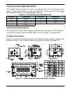
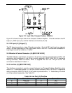
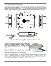
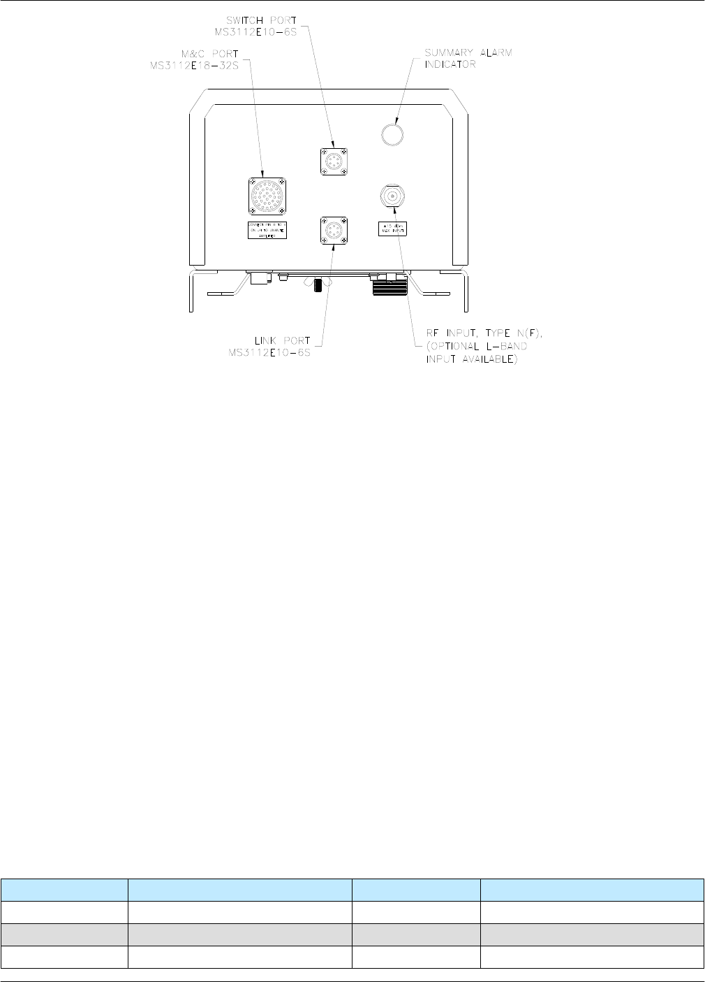
Figure 2-2 shows the input side of the Compact Outdoor Amplifier. This side contains the RF
input (J1), M&C input (J4), and the Interface connections (J5, J6).
2.5.1 RF Input (J1) [N-type (F)]
The RF Input connector is a type N female connector. Nominal RF input levels are approxi-
mately -28 dBm depending on the output power level of the unit. The maximum allowable RF
input signal should be limited to +15 dBm.
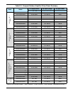
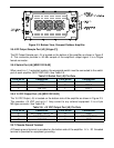
2.5.2 Monitor & Control Connector (J4) [MS3112E18-32S]
The M&C, Monitor and Control, connector is the primary input for controlling the amplifier and
monitoring fault conditions. It is a 32-pin circular connector, MS3112E18-32S. It requires a
mating connector, MS3116F18-32P, which is supplied with the unit. The pin-out for this
connector is described in Table 3-1.
2.5.3 Link Port (J5) [MS3112E10-6S]
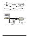
The interface connector is used to connect between two Compact Outdoor Amplifiers when
used in a 1:1 redundant system. It is a 6 pin circular connector, MS3112E10-6S. It requires a
mating connector, MS3116F10-6P. A link cable is provided with a 1:1 Redundancy Kit which
can be purchased separately. See Table 2-4.
Table 2-4: Link Port (J5) Pin-Outs
Pin # on J5 Connection Pin # on J5 Connection
A LINK OUT D N/C
B LINK IN E N/C
C N/C F GND
Figure 2-2: Input Side, Compact Outdoor Amplifier
SWITCH
M & C
J4
STATUS
SSPA
RF IN
J6
J1
J5
LINK