


Operations Manual, HPA2, Compact Outdoor SSPA 205486 REV F 41
5.0 Introduction
This section describes some of the standard RF tests performed on production amplifiers
before shipment. Where possible Paradise Datacom, LLC maintains computer automated RF
test stations to ensure a high level of accuracy and consistency to production amplifier
testing.
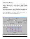
5.1 Gain and Gain Flatness
The amplifier gain is swept over the operating frequency range under small signal conditions
to confirm the minimum gain and gain flatness specifications. The entire Compact Outdoor
Amplifier is tested in a temperature chamber from -40°C to +55°C; and the gain is recorded.
5.2 P
1dB
The 1 dB Gain Compression Point is measured at discrete frequencies across the band to
characterize the output power over the operating frequency range. The P
1dB
is a guaranteed
minimum specification.
5.3 Input and Output Return Loss
The input and output return loss are measured in all production amplifiers. This is a measure
of how closely the amplifier is matched to its characteristic impedance. The input impedance
of the amplifier is a nominal 50 ohms while the output is matched to the waveguide complex
impedance.
5.4 Spurious
Spurious signals are undesirable byproducts of amplifiers caused by nonlinearities within the
amplifier and other system level components such as switch mode power supplies. These
unwanted signals cause signal management problems in system applications. Out of band
spurious signals cause interference to other pieces of equipment.
5.5 RF Sample Port
The RF Sample port is measured at discrete frequencies across the band and a calibration
label is placed near the type N connector on the bottom of the unit. The sample port is
approximately -40 dB down from the RF output. A label with the exact coupling ratio is
attached to the amplifier chassis.
Section 5: Performance Tests