


32 205486 REV F Operations Manual, HPA2, Compact Outdoor SSPA
RX Checksum Alarm: The RX Checksum Alarm indicates when an invalid checksum byte is
communicated to the unit.
External Mute Alarm: The External (Ext) Mute line gives an indication via the M&C screen
that the SSPA has been externally muted by J4-Pin B. This external mute alarm can be
configured to trigger a summary alarm if desired. The factory default is to signal a External
Mute fault but no Summary Alarm.
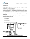
RF Switch Alarms: The RF Switch 1 Alarm is only active if a 1:1 Redundant System has
been configured in the M&C program. The RF Switch 2 Alarm is only active is a 1:2
Redundant System has been configured. These configuration are covered in Section 7, the
Redundant System Concepts description.
All of the above alarms, with the exception of the RF Switch and External Mute Alarms, are
available as open collector outputs and Form C relays on the J4 parallel interface.
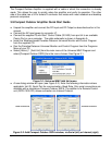
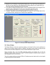
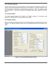
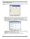
3.9.1.3 Voltage, Current and Temperature Display
On the right side of the Status window there is a thermometer display that reports the present
baseplate temperature of the amplifier. The baseplate temperature typically experiences a 20
to 30 degree rise above ambient on the highest power Compact Outdoor Amplifiers and 15 to
20 degree rise on lower power units.
To the left of the thermometer display are several indicators that show various operating
conditions of the Compact Outdoor Amplifier in real time. These indicators are helpful for any
diagnostic proceedures. Among the horizontal indicators include:
• Power Supply Voltage
• SSPA DC Current
• Regulator Voltage
• Gate Voltage
The Power Supply voltage monitors the primary 12 volt power supply output. SSPA Current is
the total current drawn by the microwave transistors. Regulator Voltage is the DC voltage of
the drain circuitry that feeds the GaAs transistors. The Gate Voltage indicator monitors the
DC voltage of the gate circuitry of the microwave GaAs transistors. These indicators provide
direct access to the active device operating characteristics.
3.9.1.4 Gain Adjustment
The Gain Attenuation Control is located above the Fault Condition Indicators and to the right
of the Carrier Enable status. The gain can be adjusted by setting the Attenuation Control. An
Attenuation Control of 0 dB is the maximum gain (75 dB) setting on the amplifier. By setting
the Attenuation Control to 20 dB; the gain is set to (55 dB). The Attenuation Control can be
varied using the control knob or the forward/reverse buttons.
Note the illuminated PC Control button inside the Attenuation Control frame. This control
allows the gain adjustment function to be assigned to the analog input voltage (J4-Pin A). The
gain adjustment control must be either under PC control or analog voltage control; it cannot
be both.