


Operations Manual, HPA2, Compact Outdoor SSPA 205486 REV F 3
Section 1: General Information .......................................................................................... 9
1.0 Introduction ........................................................................................................... 9
1.1 Description ............................................................................................................ 9
1.2 Specifications ........................................................................................................ 9
1.3 Equipment Supplied .............................................................................................. 9
1.4 Safety Considerations ......................................................................................... 10
1.4.1 High Voltage Hazards ........................................................................... 10
1.4.2 RF Transmission Hazards .................................................................... 10
Section 2: Installation ........................................................................................................ 11
2.0 Introduction ......................................................................................................... 11
2.1 Inspection ........................................................................................................... 11
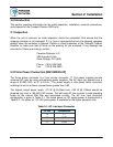
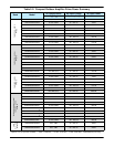
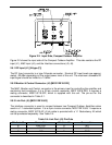
2.2 Prime Power Connection [MS3102E20-3P] ........................................................ 11
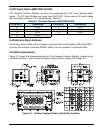
2.3 DC Input Option [MS3102E-20-29P] ................................................................... 13
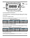
2.4 Summary Alarm Indicator ................................................................................... 13
2.5 Cable Connections .............................................................................................. 13
2.5.1 RF Input (J1) [N-type (F)] ...................................................................... 14
2.5.2 Monitor & Control Connector (J4) [MS3112E18-32S] ........................... 14
2.5.3 Link Port (J5) [MS3112E10-6S] ............................................................. 14
2.5.4 RF Output Sample Port (J3) [N-type (F)] ............................................... 15
2.5.5 Switch Port (J6) [MS3112E10-6S] ......................................................... 15
2.5.6 15 VDC Output Port (J8) [MS3112E10-6S] ........................................... 15
2.5.7 Chassis Ground Terminal ...................................................................... 15
2.5.8 AC Input (J7) ........................................................................................ 16
2.5.9 RF Output (J2) ...................................................................................... 16
2.6 Airflow ................................................................................................................. 16
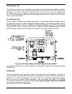
2.7 Fiber-Optic Option ............................................................................................... 17
2.7.1 RCPF-1000 Fiber Optic Controller ........................................................ 17
2.7.2 External L-Band to Fiber Interface ........................................................ 18
2.8 Unit Weights........................................................................................................ 20
2.9 Compact Outdoor Mounting Kit Installation ......................................................... 21
2.9.1 Safety Considerations ........................................................................... 21
2.9.2 Inspection .............................................................................................. 21
2.9.3 Installation ............................................................................................. 22
Section 3: Operation .......................................................................................................... 25
3.0 Introduction ......................................................................................................... 25
3.1 RF Input (J1) ....................................................................................................... 25
3.2 RF Output (J2) .................................................................................................... 25
3.3 Amplifier Enable (Mute/Unmute) (J4) .................................................................. 25
3.4 Alarms (J4) .......................................................................................................... 27
3.4.1 Summary Alarm
(J4) Form C Contacts ................................................. 27
3.4.2 Auxiliary Alarm (J4) Form C Contacts ................................................... 27
3.4.3 Open Collector Alarm Outputs (J4) ....................................................... 27
3.5 RF Power Detector (J4) ...................................................................................... 28
Table of Contents