


-6-
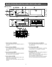
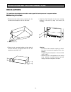
54. Cooling fan
Prevents temperature rise inside the unit.
55. AC socket
For connecting the supplied power cord.
56. Power switch (POWER ON/OFF)
Turns the power of the Disc Recorder on and off.
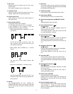
*
1
: A “record” is a batch of freeze pictures (frames)
recorded in one recording session.
*
2
: One recorded freeze picture is called a “frame”.
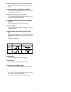
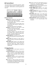
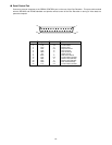
Alarm
Output
Alarm
Recover
Output
HL
12 V
0 V
5 V
0 V
5 V
0 V
5 V
0 V
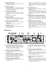
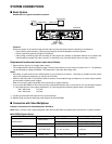
48. Audio Output/Input connectors (AUDIO OUT/IN)
Provided for recording and playback of audio sig-
nals.
49. Parallel Control port (PARALLEL CONTROL)
For connecting an outboard device used to remote
control the Disc Recorder.
50. Serial Control port (SERIAL CONTROL)
For connecting a Personal Computer and the like to
remote control the Disc Recorder.
51. Camera Switching Output connector (CAMERA
SW OUT)
Outputs a pulse after each recorded frame.
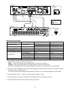
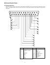
52. Terminal Board
For connecting output and input signals to and from
outboard devices.
53. Alarm Output Level selector (OUTPUT LEVEL
H/L)
Switches the output level of the ALARM OUT and
ALARM RECOVER terminals on the Terminal Board
(52).
The factory default is L.