


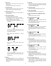
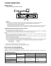
WJ-DR200 Setup Menu
VIDEO INPUT
-8-
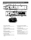
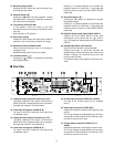
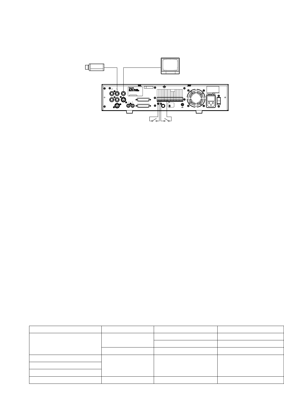
SYSTEM CONNECTIONS
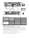
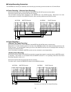
■ Basic System
Shown below is a typical connection scenario.
CAUTION
- FOR CONTINUED PROTECTION
Manufactured by Matushita Communication
Industrial Co. Ltd Yokohama Japan
- AFIN D' ASSURER UNE
ATTENTION
AGAINST FIRE HAZARD REPLACE ONLY WITH
SAME TYPE FUSE
PROTECTION PERMANENTE CONTRE LES RISQUES
D' INCENDIE REPLACER UNIQUEMENT PAR UN
FUSIBLE DE MEME TYPE
POWER 120V AC 60 Hz 38W
VIDEO OUT 1V [ p-p ] 75Ω
FOR COMMERCIAL USE ONLY
Made In Japan
SIGNAL GND
120V AC 60Hz
OFF
125V 4 A
POWER
ON
GND
SENSOR IN
ALARM IN
ALARM RESET IN
SERIES REC IN
TIME ADJUST IN
GND
ALARM OUT
ALARM RECOVER OUT
ALARM REC
REC
DISC
BUZZER OUT
SYSTEM ERROR OUT
THERMAL ERROR OUT
TIME ADJUST OUT
SERIES REC OUT
LED
MONITOR
CAMERA SW OUT
AUDIO
PARALELL CONTROL
SERIAL CONTROL
IN
OUT
S-VIDEO
OUT
S-VIDEO
VIDEO OUT
VIDEO IN
BA
SER.
NO.
6ZA00001
OUTPUT LEVEL
H
L
Camera
Video Monitor
(Alarm)(Sensor)
(VIDEO OUT)
(VIDEO IN)
WJ-DR200
Requirements for alarm and sensor input are as follows:
• Open collector output or no-voltage make contact
• The voltage between Ground and Alarm Input or Sensor Input when the circuit closes must be 0 to 0.2 V. The polarities
can be changed by setting the SIGNAL TYPE parameter in the Alarm Recording menu.
Notes:
• Recording of freeze pictures from VCR playback is not provided as a function. Recording is possible, but the results
may not be satisfactory depending on the type of VCR used.
• When the Disc Recorder is connected to several cameras, for example through a multiplexer, all camera inputs must be
synchronized to obtain proper images.
Refer all connection work to qualified service personnel or system installers.
• If you use the WJ-DR200 AV Disc Recorder with a Sequential Switcher that is connected to non-synchronized cameras
(*1) and switches their video output sequentially (*2), recording with the following capture rates is not available:
720
*
480 mode 0.07 sec.
720
*
240 mode 0.03 sec.
*1: Including cameras with VD (Vertical Drive) synchronization.
*2: Without using the camera switching pulse supplied by the WJ-DR200.
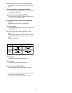
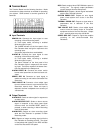
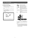
■ Connection with Video Multiplexer
Example: Connection with Video Multiplexer WJ-FS616
Note: Refer connection with a Video Multiplexer other than the WJ-FS616 to qualified service personnel or system installers.
MULTI SHOT (MODE *)
TIME LAPSE (MODE *)
MANUAL REC ALARM
SERIAL SETUP
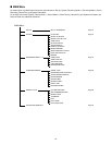
Item
VIDEO INPUT
CAPTURE RATE
CAMERA INPUT
SIGNAL TYPE
Parameter
COMPOSITE *1
0.1 sec. or more
A (CAMERA ID ON)
RS-232C (VCR mode) *3
Default Setting
COMPOSITE
S *1 COMPOSITE
0.20 sec.
A (CAMERA ID OFF)
RS-232C
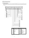
● WJ-DR200 System Setup
Cautions:
Noise may appear in the monitor image and the audio may be interrupted under the following circumstances:
• Faulty camera synchronization, causing large frequency deviations between individual cameras
• Picture experiencing abrupt changes in brightness
• Faulty timing in switching input and recording of video signals (for example, a sequential switcher is not used for the
camera switching output of the disc recorder, or switching is out of synchronization due to an alarm condition)