


-18-
A (CAMERA ID ON): Records only input A with
multiplexed Camera ID signals.
Use this parameter when the Disc Recorder is
connected to a Video Multiplexer. You can
select camera images in playback mode. The
video pixel number (resolution) is fixed at 720
*
240.
A (CAMERA ID OFF): Records only input A without
multiplexed Camera ID signals.
A+B (CAMERA ID OFF): Records input A and B
without multiplexed Camera ID signals.
Use this parameter when two cameras are con-
nected to the Disc Recorder.
Note: When two recording inputs are selected,
audio recording is disabled in Multi Shot and
Time Lapse Recording mode.
The default setting is A (CAMERA ID OFF).
6. Move the cursor to the CAMERA TYPE parameter by
pressing the or button.
7. Select the parameter according to the connected
camera by pressing the or button.
COLOR: Select this mode when a color camera
other than a line-locked camera is connected for
input.
COLOR LL: Select this mode when a line-locked
color camera is connected for input.
B/W: Select this mode when a black and white cam-
era other than a line-licked camera is connected
for input.
B/W LL: Select this mode when a line-locked black
and white camera is connected for input.
Note: If the CAMERA INPUT item on the same menu
is set to A (CAMERA ID ON), neither the COLOR
LL nor B/W LL parameter of the CAMERA TYPE
item will be displayed (cannot be set).
Precautions in Using a Line-locked Camera
1. With a line-locked camera, horizontal stripes
may appear in recorded images despite the
above settings.
2. With an S-video output camera, monochrome
images will be monitored in standby mode when
COLOR LL is selected on the above menu, but
will be recorded normally.
3. If the CAMERA TYPE parameter COLOR is
selected on the above menu, recorded images
may be subject to disturbance or the number of
frames recorded may be different from the set
number.
4. If you are connecting the WJ-DR200 AV Disc
Recorder to the Spot Output (or Camera Output)
of a sequential switcher or video multiplexer to
which a line-locked camera is connected, be
sure to select the CAMERA TYPE parameter
Line Lock.
The default setting is COLOR.
8. Move the cursor to the INPUT CHECK parameter by
pressing the or button.
9. Press the or button to display the video
selected with this parameter.
This function is available only when the CAMERA
INPUT parameter is set to A+B (CAMERA ID OFF) in
this menu.
10. Press the SET UP/ESC button to return to the SYS-
TEM menu.
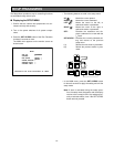
● Status Display Setup
This item lets you enable or disable status display or
embedded display on the monitor screen.
1. Move the cursor to the STATUS DISPLAY parameter
in the SYSTEM menu by pressing the or
button.
2. Select the desired mode by pressing the or
button.
ON: Enables status display on the monitor screen.
OFF: Enables status display for two seconds on the
monitor screen every time the status changes.
EMBEDDED: Enables time and date display only in
recording mode and status display in playback
mode.
The default setting is ON.
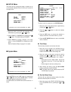
● Alarm Display Setup
This item lets you enable or disable alarm display on the
monitor screen.
1. Move the cursor to the ALARM DISPLAY parameter
in the SYSTEM menu by pressing the or
button.
2. Select either ON or OFF by pressing the or
button.
ON: Enables alarm display on the monitor screen.
OFF: Disables alarm display on the monitor screen
The default setting is ON.
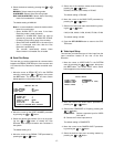
● Display Position Setup
This item lets you select the positions where the alarm
and status displays are placed on the monitor screen.
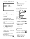
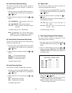
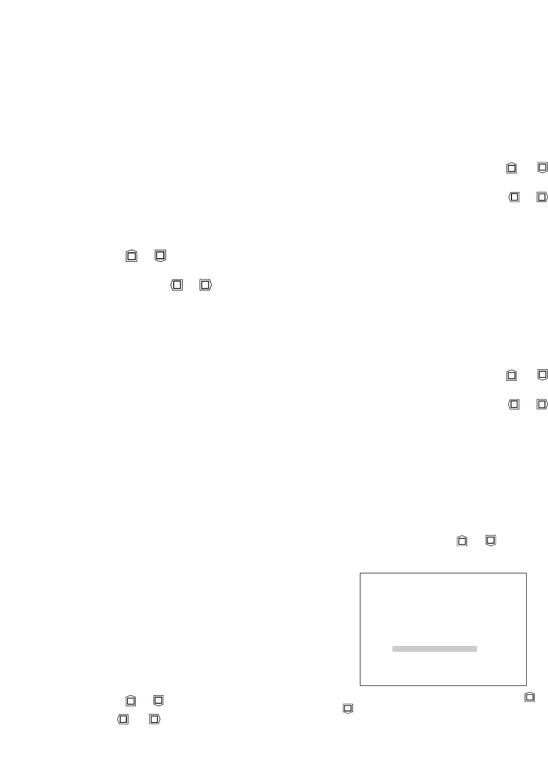
1. Move the cursor to DISPLAY POSITION in the SYS-
TEM menu by pressing the or button, then
press the SET button. The position setup menu
shown below appears on the monitor screen.
PRESS SET_UP/ESC KEY
↑=MOVE UP ↓=MOVE DOWN
RECORD-# STATUS WARNING
YY-MM-DD HH:MM:SS LABEL
2. Move the display position by pressing the or
button, then press the SET UP/ESC but-
ton to execute the selection and return to the SYS-
TEM menu.