


-5-
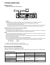
CAUTION
- FOR CONTINUED PROTECTION
Manufactured by Matushita Communication
Industrial Co. Ltd Yokohama Japan
- AFIN D' ASSURER UNE
ATTENTION
AGAINST FIRE HAZARD REPLACE ONLY WITH
SAME TYPE FUSE
PROTECTION PERMANENTE CONTRE LES RISQUES
D' INCENDIE REPLACER UNIQUEMENT PAR UN
FUSIBLE DE MEME TYPE
POWER 120V AC 60 Hz 38W
VIDEO OUT 1V [ p-p ] 75Ω
FOR COMMERCIAL USE ONLY
Made In Japan
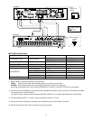
SIGNAL GND
120V AC 60Hz
OFF
125V 4 A
POWER
ON
GND
SENSOR IN
ALARM IN
ALARM RESET IN
SERIES REC IN
TIME ADJUST IN
GND
ALARM OUT
ALARM RECOVER OUT
ALARM REC
REC
DISC
BUZZER OUT
SYSTEM ERROR OUT
THERMAL ERROR OUT
TIME ADJUST OUT
SERIES REC OUT
LED
MONITOR
CAMERA SW OUT
AUDIO
PARALELL CONTROL
SERIAL CONTROL
IN
OUT
S-VIDEO
OUT
S-VIDEO
VIDEO OUT
VIDEO IN
BA
SER.
NO.
6ZA00001
OUTPUT LEVEL
H
L
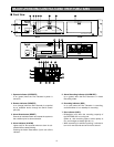
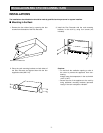
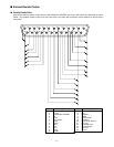
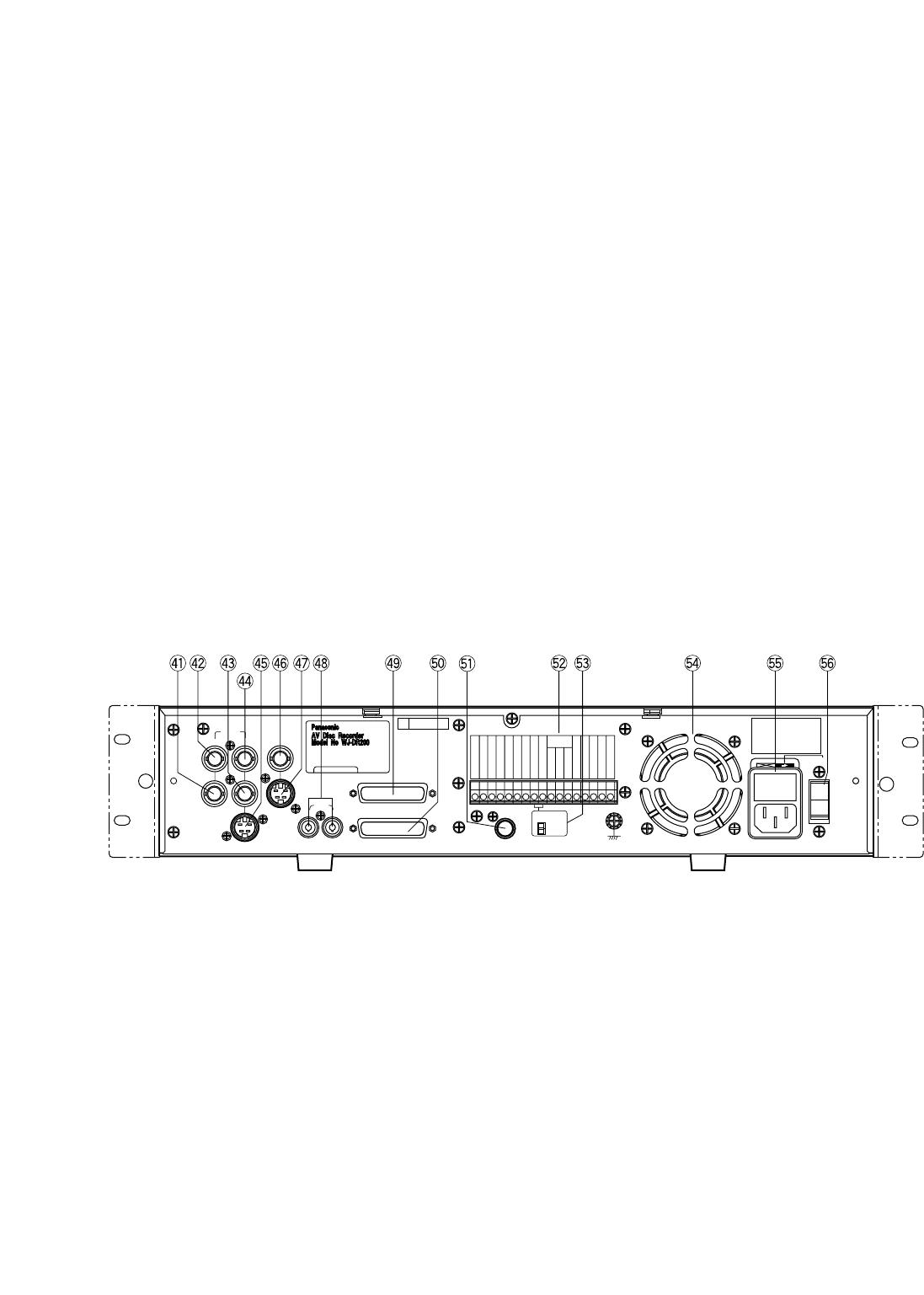
■ Rear View
41. Looped Through Output B connector (B, OUT)
The NTSC composite video signal B connected to
VIDEO IN B (42) is looped through to this connector.
Provided with automatic 75 Ω termination.
42. Video Input B connector (VIDEO IN, B)
For input of the NTSC composite video signal from
an outboard device.
43. Looped Through Output A connector (A, OUT)
The NTSC composite video signal A connected to
VIDEO IN A (44) is looped through to this connector.
Provided with automatic 75 Ω termination.
44. Video Input A connector (VIDEO IN, A)
For input of the NTSC composite video signal from
an outboard device.
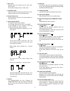
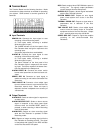
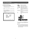
31. Recording button (REC)
Pressing the REC button will start recording in the
previously defined mode.
32. Playback button (BB)
Pressing the (BB) button will start playback. Holding
the button down will speed up playback, releasing it
will restore the normal speed.
33. Lock switch (LOCK OFF/ON)
In ON position, locks out control of the Disc
Recorder from the Control Panel and Parallel Control
port (49).
Keep normally in OFF position.
34. Stop button (STOP)
Pressing the STOP button will terminate all modes of
operation, such as recording, playback and setup.
35. Open/Close button (OPEN/CLOSE)
Press to slide the disc tray out or in for loading or
unloading a disc.
Disabled while the Disc Cover (8) is closed.
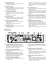
36. Increment button (DD+)
Pressing the (DD+) button in playback will decrease
the playback speed.
Pressing it in paused playback will increment the
playback channel (or camera ID). To play back the
selected channel, press the PLAY BACK SELECT
button (38).
37. Decrement button (CC–)
Pressing the (CC–) button in playback will increase
the playback speed.
Pressing it in paused playback will decrement the
playback channel (or camera ID). To play back the
selected channel, press the PLAY BACK SELECT
button (38).
38. Playback Select button (PLAY BACK SELECT)
Pressing the PLAY BACK SELECT button after
selecting the input channel with the (DD+) (36) or
(CC–) (37) button will start playback of the respective
channel.
39. Setup/Escape button (SET UP/ESC)
Used in the Disc Recorder’s setup operation.
Pressing the button for about two seconds will
establish Setup mode and display the Setup menu
window. Pressing it in a menu will return you to the
previous menu window.
To terminate setup, press again for about two sec-
onds.
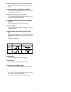
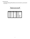
45. S-Video Input connector (VIDEO IN, S-VIDEO)
For input of the S-video signal from an outboard
device.
46. Video Output connector (VIDEO OUT)
Outputs the selected composite video signal for the
monitor.
The A input images are displayed during recording,
except when A and B inputs are recorded at a cap-
ture rate of one second or more.
47. S-Video Output connector (VIDEO OUT, S-
VIDEO)
Outputs the selected S- video signal for the monitor.
The A input images are displayed during recording,
except when A and B inputs are recorded at a cap-
ture rate of one second or more.