


5 - 8
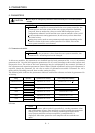
5. PARAMETERS
Classifi-
cation
No. Symbol Name and Function
Initial
Value
Unit
Setting
Range
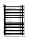
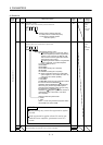
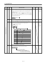
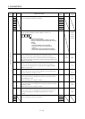
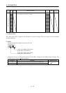
20 INP In-position range
Used to set the droop pulse range in which the in-position (INP) will
be output to the controller. Make setting in the feedback pulse unit
(parameter No. 6).
For example, when you want to set
10 m in the conditions that the
ball screw is direct coupled, the lead is 10mm, and the feedback
pulses are 8192 pulses/rev (parameter No. 6 : 1), set "8" as indicated
by the following expression.
10 10
6
10 10
3
8192 8.192 8
100 pulse 0
to
50000
21 MBR Electromagnetic brake sequence output
Used to set a time delay (Tb) from when the electromagnetic brake
interlock signal (MBR) turns off until the base circuit is shut off.
0ms0
to
1000
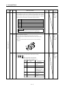
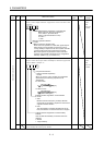
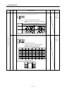
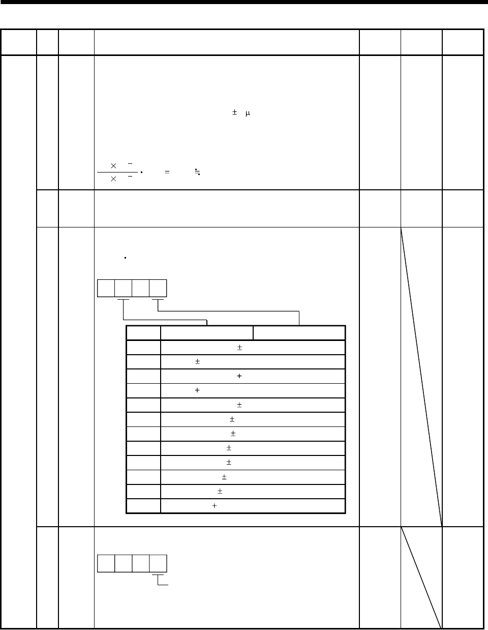
22 MOD Analog monitor output
Used to select the signal provided to the analog monitor
(MO1)
analog monitor (MO2).
(Refer to section 5.3.)
Analog monitor1 (MO1)
Setting
0 Servo motor speed ( 8V/max. speed)
1 Torque ( 8V/max. torque) (Note)
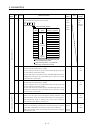
2 Servo motor speed ( 8V/max. speed)
3 Torque ( 8V/max. torque)
(Note)
4 Current command ( 8V/max. current command)
5 Speed command ( 8/max. speed)
6 Droop pulses ( 10V/128 pulses)
7 Droop pulses ( 10V/2048 pulses)
8 Droop pulses ( 10V/8192 pulses)
9 Droop pulses ( 10V/32768 pulses)
A Droop pulses ( 10V/131072 pulses)
00
B Bus voltage ( 8V/400V)
Analog monitor2 (MO2)
Note. 8V is outputted at the maximum torque.
0001 Refer to
name
and
function
column.
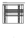
Adjustment parameters
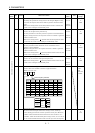
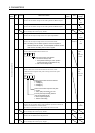
23 *OP1 Optional function 1
Used to make the servo forced stop function invalid.
Servo forced stop selection
0: Valid (Use the forced stop (EM1).)
1: Invalid (Do not use the forced stop (EM1).)
Automatically switched on internally
000
0000 Refer to
name
and
function
column.