


3 - 4
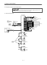
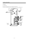
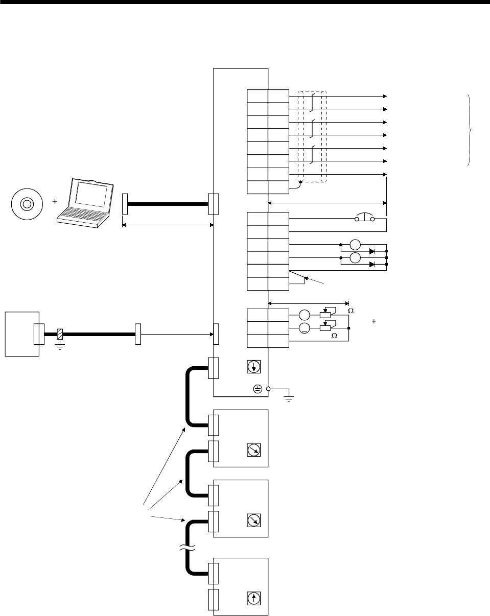
3. SIGNALS AND WIRING
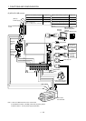
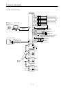
3.1.2 MR-J2S-11KB or more
(Note 3, 6)
CN3
CN1A
CN1B
10k
10k
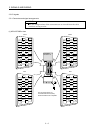
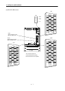
SW1
Setting : 0
SW1
Setting : 2
SW1
Setting : 1
MR-J2S-B
(2 axis)
CN1A
CN1B
MR-J2S-B
(3 axis)
CN1A
CN1B
SW1
Setting: n-1
MR-J2S-B
(n axis)
CN1A
CN1B
n= 1 to 8
(Note 9)
(Note 10)
(Note 9)
(Note 9)
(Note 11)
MR-A-TM
(Note 4)
(Note 4)
Magnetic brake
interlock
Forced stop
(Note 2, 5)
Plate
Servo amplifier
(Note 4)
Cable clamp
(Option)
(Note 8, 12)
Bus cable (Option)
Servo system controller
(Note 1)
(Note 7)
MR Configurator
(Servo configuration
software)
Personal computer
15m(49.2ft)
or less
(Note 8, 12)
Bus cable
(Option)
Analog monitor
Max. 1mA
Reading in
both directions
2m(6.56ft) or less
Encoder A-phase pulse
(differential line driver)
Encoder B-phase pulse
(differential line driver)
Encoder Z-phase pulse
(differential line driver)
(Note
13)
Dynamic brake
interlock
1
2
4
MO1
MO2
LG
CN4
2
1
4
EM1
SG
DB
CON2
3 MBR
18 COM
15 VDD
6
16
7
LA
LAR
LB
CN3
17
8
LBR
LZ
18 LZR
SD
LG
10m(32.81ft) or less
1
When using the forced stop (EM1), magnetic
brake interlock (MBR) or dynamic brake
interlock (DB), make sure to connect it.
RA1
RA2
A
A