


3 - 8
3. SIGNALS AND WIRING
3.2.2 Signal explanations
For the I/O interfaces (symbols in I/O column in the table), refer to section 3.4.2.
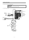
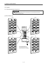
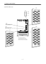
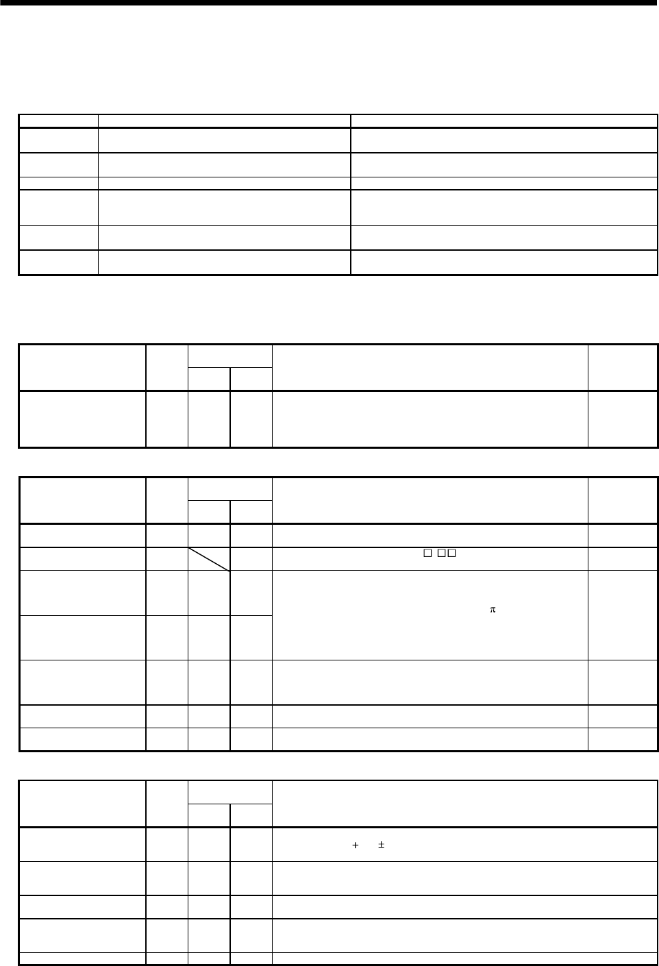
(1) Connector applications
Connector Name Function/Application
CN1A Connector for bus cable from preceding axis.
Used for connection with the controller or preceding-axis
servo amplifier.
CN1B Connector for bus cable to next axis
Used for connection with the next-axis servo amplifier or
for connection of the termination connector.
CN2 Encoder connector Used for connection with the servo motor encoder.
CN3
Communication connector
(I/O signal connector)
Used for connection with the personal computer.
Serves as an I/O signal connector when the personal
computer is not used.
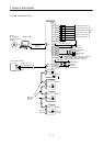
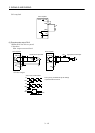
(Note) CN4 Analog monitor output connector
Used to output analog monitor 1 (MO1) and analog monitor
2 (MO2).
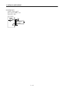
(Note) CON2 IO signal connector
Used to input a forced stop and output the dynamic brake
interlock(DB), the electromagnetic brake interlock
Note. These connectors are exclusive to the MR-J2S-11KB or more.
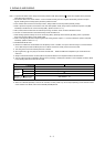
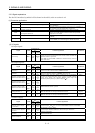
(2) I/O signals
(a) Input signal
Connector Pin
No.
Signal S
y
mbol
7kW
or less
11kW
or more
Function/Application I/O Division
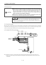
Forced stop EM1
CN3
20
CON2
2
Turn EM1 off (open EM1 common) to brin
g
the motor to a
forced stop state, in which the base circuit is shut off and the
dynamic brake is operated.
Turn EM1 on (short EM1 common) in the forced stop state to
reset that state.
DI-1
(b) Output signals
Connector Pin
No.
Signal S
y
mbol
7kW
or less
11kW
or more
Function/Application I/O Division
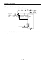
Electromagnetic brake
interlock
MBR
CN3
13
CON2
3
In the servo-off or alarm status, MBR turns off.
DO-1
Dynamic brake
interlock
DB
CON2
4
When usin
g
this si
g
nal, set 1
in the parameter No. 2.
When the dynamic brake is operated, DB turns off.
DO-1
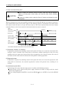
Encoder A-phase pulse
(Differential line driver)
LA
LAR
CN3
6
CN3
16
CN3
6
CN3
16
Encoder B-phase pulse
(Differential line driver)
LB
LBR
CN3
7
CN3
17
CN3
7
CN3
17
Outputs pulses per servo motor revolution set in parameter
No.38 in the differential line driver s
y
stem. In CCW rotation
of the servo motor, the encoder B-phase pulse la
g
s the
encoder A-phase pulse by a phase angle of
/2.
DO-2
Encoder Z-phase pulse
(Differential line driver)
LZ
LZR
CN3
8
CN3
18
CN3
8
CN3
18
The zero-phase si
g
nal of the encoder is output in the
differential line driver system.
DO-2
Analog monitor 1 MO1
CN3
4
CN4
1
Used to output the data set in parameter No.22 to across
MO1-LG in terms of voltage. Resolution 10 bits
Analog
output
Analog monitor 2 MO2
CN3
14
CN4
2
Used to output the data set in parameter No.22 to across
MO2-LG in terms of voltage. Resolution 10 bits
Analog
output
(c) Power supply
Connector Pin
No.
Signal S
y
mbol
7kW
or less
11kW
or more
Function/Application
Internal power output
for interface
VDD
CN3
10
CON2
15
Driver power output terminal for digital interface.
Used to output
24V 10% to across VDD-COM. Connect with COM.
Permissible current: 80mA
Power input for digital
interface
COM
CN3
5
CON2
18
Driver power input terminal for digital interface.
Used to input 24VDC (200mA or more) for input interface.
Connect with VDD.
Common for digital
interface
SG
CN3
3
CON2
1
Common terminal to VDD and COM. Pins are connected internally.
Separated from LG.
Control common LG
CN3
1
11
CN4
4
Common terminal to MO1 and MO2.
Shield SD Plate Plate Connect the external conductor of the shield cable.