


3 - 33
3. SIGNALS AND WIRING
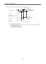
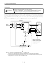
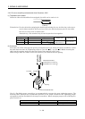
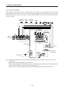
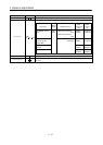
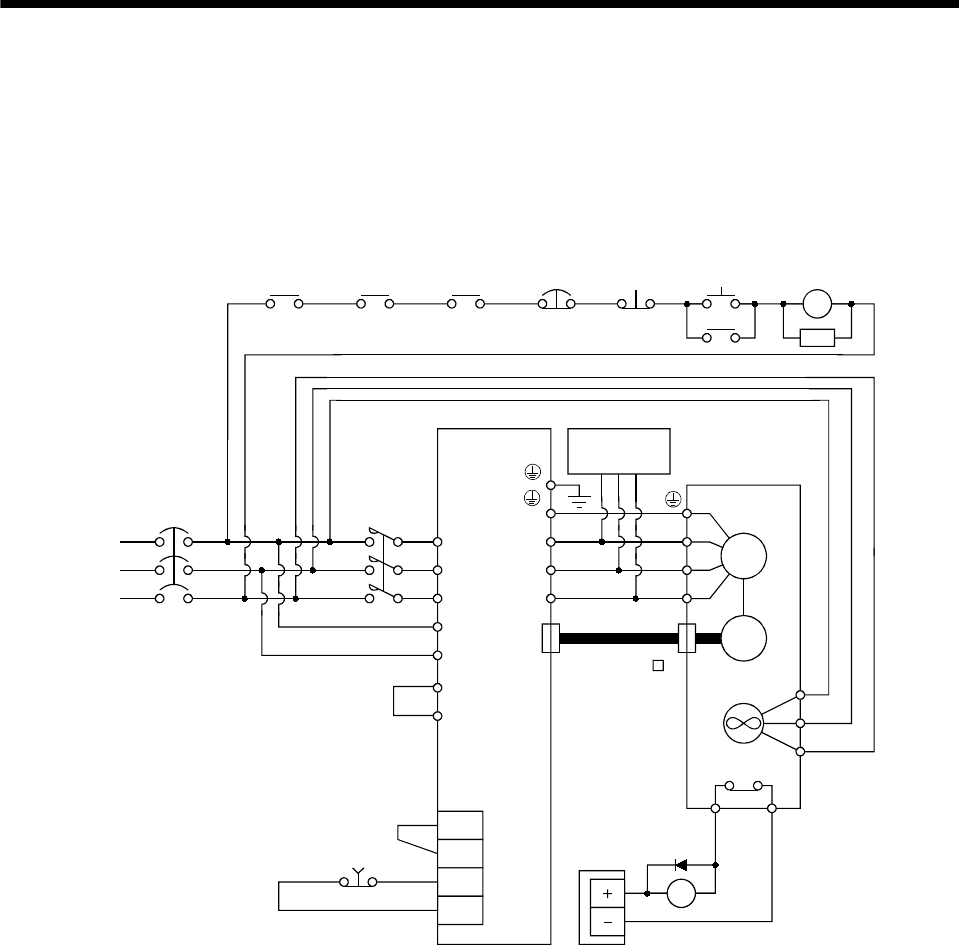
3.12.1 Connection example
Wire the power supply/main circuit as shown below so that power is shut off and the servo-on signal
turned off as soon as an alarm occurs, a servo forced stop is made valid, a controller forced stop, or a servo
motor thermal relay alarm is made valid. A no-fuse breaker (NFB) must be used with the input cables of
the power supply.
(Note 1)
Alarm
RA1
Controller
forced stop
RA2
L
1
L2
L3
L11
L21
VDD
COM
EM1
SG
Servo amplifier
CN2
U
V
W
U
V
W
Dynamic
break
Servo motor
HA-LFS series
M
Encoder
BU
Cooling fan
RA3
24VDC
power supply
MR-JHSCBL M
cable
BV
BW
MC
SK
ON
MC
OFF
Forced
stop
Servo motor
thermal relay
RA3
NFB MC
Forced stop
OHS2OHS1
Servo motor
thermal relay
(Note 3)
3-phase
200 to 230V
(Note 2)
P1
P
(Note 4)
Note 1. Configure up the power supply circuit which switches off the magnetic contactor after detection of alarm occurrence on the
controller side.
2. When using the external dynamic break, refer to section 12.1.4.
3. Cooling fan power supply of the HA-LFS11K2 servo motor is 1-phase. Power supply specification of the cooling fan is different
from that of the servo amplifier. Therefore, separate power supply is required.
4. Always connect P
1 and P. (Factory-wired.) When using the power factor improving DC reactor, refer to section 12.2.4.