3 - 12
3. SIGNALS AND WIRING
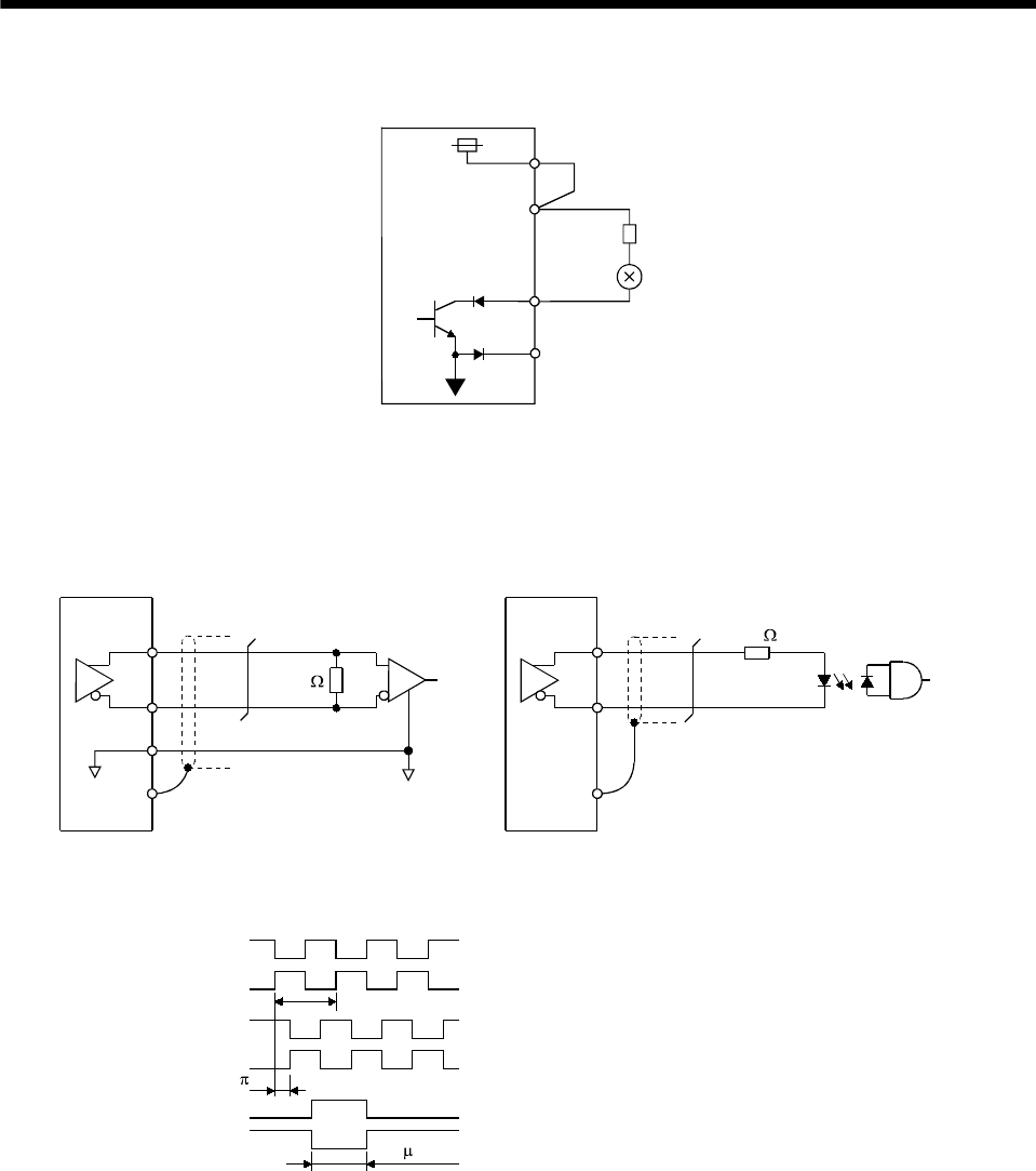
(b) Lamp load
24VDC
VDD
COM
R
MBR
SG
Servo amplifier
(3) Encoder pulse output DO-2
(Differential line driver system)
1) Interface
Max. output current: 35mA
LA
(LB, LZ)
LAR
(LBR, LZR)
LG
SD
LA
(LB, LZ)
LAR
(LBR, LZR)
SD
Servo amplifier Servo amplifier
Am26LS32 or equivalent High-speed photocouple
r
150
100
2) Pulse output
Servo motor CCW rotation
LA
LAR
LB
LBR
LZ
LZR
T
/2
400 s or more
Time cycle (T) is determined by the settings
of parameter No.33 and 38.


