


12 - 21
12. OPTIONS AND AUXILIARY EQUIPMENT
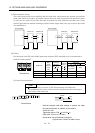
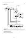
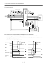
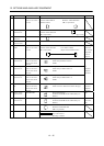
(2) Connection example
MC
NFB
MC
L11
L
21
U
V
W
U
V
W
E
M
13 U14 V W
Dynamic brake
a
b
Servo amplifier
Servo motor
SK
MC
ON
OFF
(Note 1)
Operation-ready
RA1
RA1
EM1
EM1
CON2
2
1
Plate
EM1
SG
SD
DB
CON2
15
18
VDD
COM
L
3
L
2
L
1
(Note 4)
Power
supply
4
P1
P
(Note 3)
(Note 2)
Note 1. Configure up the circuit to switch power off in the external sequence at servo alarm occurrence.
2. Terminals 13, 14 are normally open contact outputs. If the dynamic brake is seized, terminals 13, 14 will open.
Therefore, configure up an external sequence to prevent servo-on.
3. When using the servo amplifier of 11k to 22kW, make sure to connect P
1
and P. (Factory-wired.) When using the power factor
improving DC reactor, refer to section 12.2.4.
4. Refer to section 1.3 for the power supply specification.
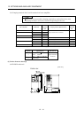
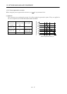
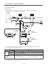
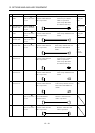
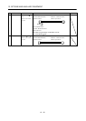
Servo motor rotation
Coasting
Alarm
RA1
ON
OFF
Forced stop
(EM1)
Absent
Invalid
Valid
Short
Open
a. Timing chart at alarm occurrence b. Timing chart at forced stop (EM1) validity
Dynamic brake
Base
ON
OFF
Coasting
Dynamic brake
Dynamic brake
Present