


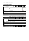
1 - 13
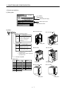
1. FUNCTIONS AND CONFIGURATION
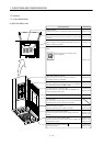
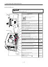
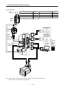
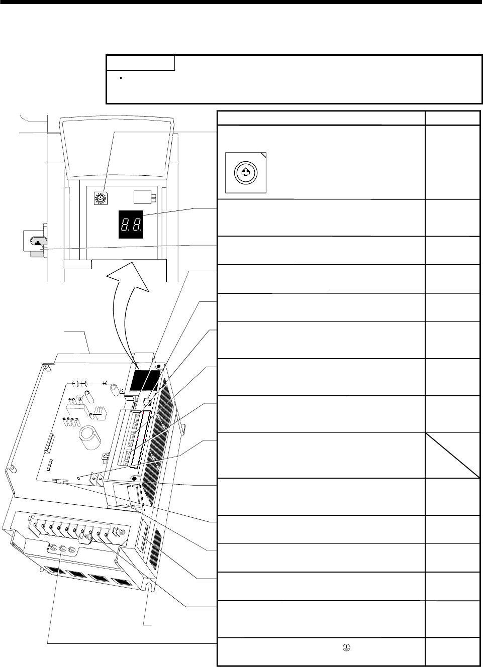
(5) MR-J2S-11KB or more
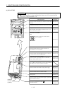
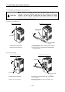
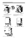
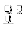
POINT
The servo amplifier is shown without the front cover. For removal of the
front cover, refer to section 1.7.2.
Fixed part
(4 places)
Cooling fan
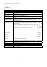
Section 3.8
Section 10.1
Reference
Chapter 4
Section 3.11
Section 3.2
Section 3.2
Section 12.1.5
Section 1.5
Section 3.2
Section 12.1.5
Section 3.5.2
Section 10.1
Section 3.5.2
Section 10.1
Section 12.1.1
Section 13.3
Section 13.3
Section 3.2
Section 3.2
Section 12.1.5
Section 3.2
Section 12.1.5
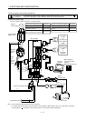
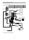
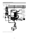
Name/Application
Axis select switch (SW1)
1
C
B
A
9
8
7
6
5
4
3
2
0
F
E
D
SW1
Used to set the axis number of
the servo amplifier.
Display
The two-digit, seven-segment LED shows the servo
status and alarm number.
Battery holder
Contains the battery for absolute position data backup.
Battery connector (CON1)
Used to connect the battery for absolute position data
backup.
Communication connector (CN3)
Used to connect a personal computer (RS-232C) .
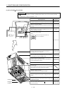
Bus cable connector (CN1A)
Used to connect the servo system controller or
preceding axis servo amplifier.
Bus cable connector (CN1B)
Used to connect the subsequent axis servo amplifier
or termination connector (MR-A-TM).
Charge lamp
Lit to indicate that the main circuit is charged. While
this lamp is lit, do not reconnect the cables.
Control circuit terminal block (TE2)
Used to connect the control circuit power supply.
Encoder connector (CN2)
Used to connect the servo motor encoder.
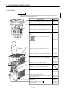
Rating plate
Main circuit terminal block (TE1)
Used to connect the input power supply, regenerative
option and servo motor.
Protective earth (PE) terminal ( )
Ground terminal.
Monitor output terminal (CN4)
Used to output monitor values on two channels in the
form of analog signals.
I/O signal connector (CON2)
Used to connect digital I/O signals.