


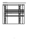
5 - 7
5. PARAMETERS
Classifi-
cation
No. Symbol Name and Function
Initial
Value
Unit
Setting
Range
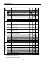
14 VG1 Speed control gain 1
Normally this parameter setting need not be changed. Higher setting
increases the response level but is liable to generate vibration and/or
noise.
When auto tuning mode 1,2 and interpolation mode is selected, the
result of auto tuning is automatically used.
7kW or
less:177
11kW or
more:96
rad/s 20
to
5000
15 PG2 Position control gain 2
Used to set the gain of the position loop.
Set this parameter to increase position response to load disturbance.
Higher setting increases the response level but is liable to generate
vibration and/or noise.
When auto tuning mode 1
2, manual mode and interpolation mode
is selected, the result of auto tuning is automatically used.
7kW or
less:35
11kW or
more:19
rad/s 1
to
1000
16 VG2 Speed control gain 2
Set this parameter when vibration occurs on machines of low
rigidity or large backlash.
Higher setting increases the response level but is liable to generate
vibration and/or noise.
When auto tuning mode 1
2 and interpolation mode is selected, the
result of auto tuning is automatically used.
7kW or
less:817
11kW or
more:455
rad/s 20
to
20000
17 VIC Speed integral compensation
Used to set the constant of integral compensation.
When auto tuning mode 1
2 and interpolation mode is selected, the
result of auto tuning is automatically used.
7kW or
less:48
11kW or
more:91
ms 1
to
1000
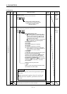
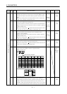
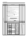
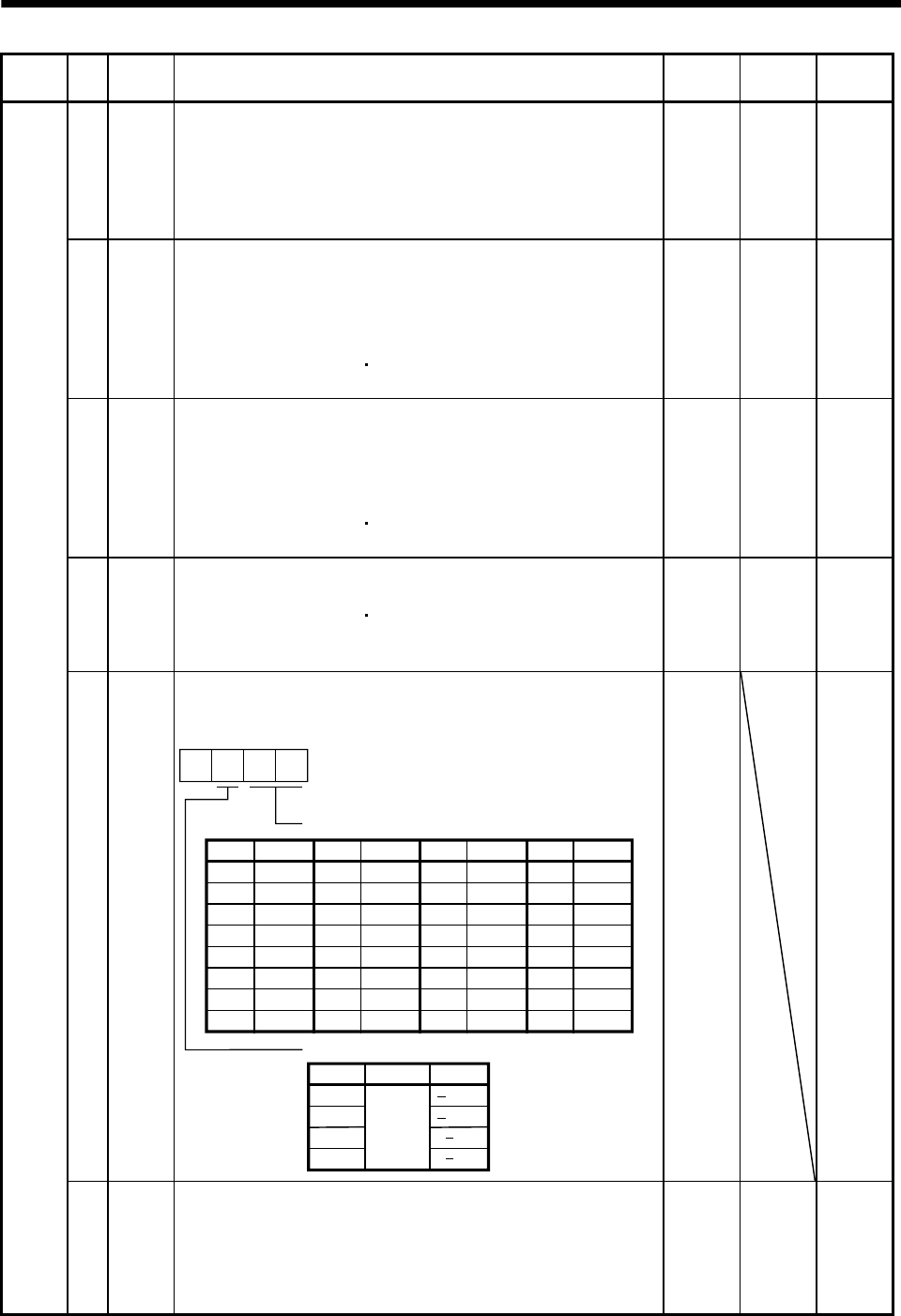
18 NCH Machine resonance suppression filter 1 (Notch filter)
Used to select the machine resonance suppression filter.
(Refer to section 7.2.)
2
3
0
0
1
Notch frequency selection
00
01
02
03
04
05
06
07
Setting
Frequency
Invalid
4500
2250
1500
1125
900
750
642.9
08
09
0A
0B
0C
0D
0E
0F
Setting
562.5
500
450
409.1
375
346.2
321.4
300
Frequency
10
11
12
13
14
15
16
17
Setting
281.3
264.7
250
236.8
225
214.3
204.5
195.7
Frequency
18
19
1A
1B
1C
1D
1E
1F
Setting
187.5
180
173.1
166.7
160.1
155.2
150
145.2
Frequency
Notch depth selection
Setting Depth Gain
Deep
Shallow
to
4dB
40dB
14dB
8dB
0000 Refer to
name
and
function
column.
Adjustment parameters
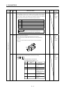
19 FFC
Feed forward gain
Set the feed forward gain. When the setting is 100%, the droop
pulses during operation at constant speed are nearly zero. However,
sudden acceleration/deceleration will increase the overshoot. As a
guideline, when the feed forward gain setting is 100%, set 1s or more
as the acceleration/deceleration time constant up to the rated speed.
0%0
to
100