


12 - 11
12. OPTIONS AND AUXILIARY EQUIPMENT
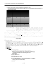
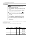
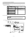
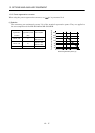
(2) Brake unit parameter setting
Normally, when using the FR-BU2, changing parameters is not necessary. Whether a parameter can
be changed or not is listed below.
Parameter
No. Name
Change
possible/
impossible
Remarks
0 Brake mode switchover Impossible Do not change the parameter.
1 Monitor display data selection Possible Refer to the FR-BU2-(H) Brake Unit
Instruction Manual.
2 Input terminal function selection 1
3 Input terminal function selection 2
77 Parameter write selection
78 Cumulative energization time
carrying-over times
CLr Parameter clear
ECL Alarm history clear
C1 For manufacturer setting
Impossible Do not change the parameter.
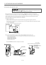
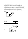
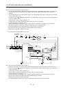
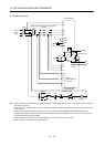
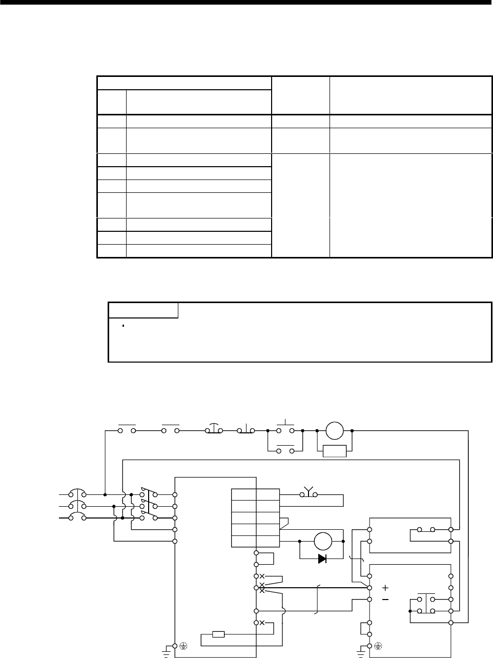
(3) Connection example
POINT
Connecting PR terminal of the brake unit to P terminal of the servo
amplifier results in brake unit malfunction. Always connect the PR
terminal of the brake unit to the PR terminal of the resistor unit.
(a) Combination with FR-BR resistor unit
NFB
ALM
RA1
MC
SK
MC
ON
OFF
EM1
Servo motor
thermal relay
RA2
(Note 7)
(Note 1)
Power
supply
N/
P/
BUE
SD
PR
B
C
A
SD
MSG
(Note 4)
(Note 6)
P
1
P
D
P
N
C
FR-BU2
FR-BR
Servo amplifier
P
PR
TH2
TH1
(Note 5)
MC
(Note 3)
(Note 8)
(Note 2)
(Note 9)
L
1
L2
L
3
L
11
L21
(Note 10)
RA1
RA1
10
5
SG
VDD
COM
ALM
3
13
CN3
EM120