


Recorder connections
02
63
En
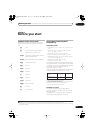
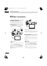
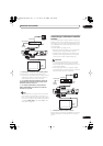
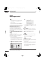
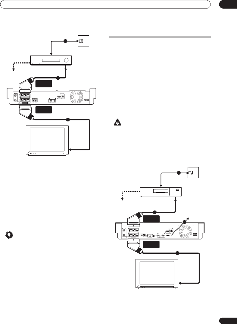
1 Connect your TV antenna to the recorder and TV.
See
Connecting a TV antenna
on page 62 for details.
• If you want to incorporate a VCR in your setup, connect
it
before
the recorder (i.e., between the antenna wall
outlet and the antenna input on the recorder).
2 Use a SCART cable (not supplied) to connect the
AV1 (RGB)-TV
AV connector on this recorder to the
SCART AV connector on your TV.
3 Use another SCART cable to connect the
AV2
(INPUT 1/DECODER)
AV connector to a SCART AV
connector on your VCR.
Tip
• This recorder has a ‘through’ function which allows
you to record a TV programme from the built-in TV
tuner in this recorder while watching a video playing
on your VCR (To use this feature when the recorder is
in standby,
Power Save
must be set to
Off
— see
Power Save
on page 152).
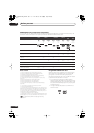
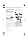
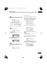
Connecting to a cable box or satellite
receiver
If you have a cable box or satellite receiver with a built-in
decoder, connect it to this recorder and your TV as shown
on this page. If you are using a separate decoder box for
your cable/satellite TV, set up following the instructions
on the next page.
Using the setup on this page you can:
• Record any channel by selecting it on the cable box,
satellite receiver or digital terrestrial receiver.
• Change channels and set timer recordings on the
external receiver using the GUIDE Plus+
®
system
(via the G-LINK™ cable, and after setting up).
Important
• Do not connect this recorder to your TV ‘through’
your VCR, satellite receiver or other component.
Always connect each component directly to your TV
or AV amplifier/receiver.
• When using the GUIDE Plus+ system to make a
timer recording from an external receiver, make sure
that the external receiver is switched on.
1 Connect RF antenna cables as shown.
See
Connecting a TV antenna
on page 62 for more on RF
antenna connections, including from this recorder to
your TV.
AC IN
DIGITAL
AUDIO OUT
COAXIAL
HDMI OUT
ANTENNA(DIGITAL)
IN
OUT
5 V
30 mA
CONTROL
G-LINK
IN
AV 1 (RGB) – TV
AV 2 (INPUT 1/DECODER)
ANTENNA
IN
OUT
VCR
TV
Antenna/cable TV
wall outlet
1
2
3
To recorder's
antenna input
From SCART AV
connector
To SCART AV
connector
AV2 (INPUT 1/
DECODER)
AV1 (RGB) - TV
From antenna output
To antenna input
AC IN
DIGITAL
AUDIO OUT
COAXIAL
HDMI OUT
ANTENNA(DIGITAL)
IN
OUT
5 V
30 mA
CONTROL
G-LINK
IN
AV 1 (RGB) – TV
AV 2 (INPUT 1/DECODER)
ANTENNA
IN
OUT
TV
Satellite dish/
antenna/cable TV
wall outlet
Cable/Satellite
receiver
To recorder's
antenna input
1
2
3
To SCART AV
connector
AV2 (INPUT 1/
DECODER)
AV1 (RGB) - TV
From antenna output
To antenna input
4
From SCART AV
connector
02SDVRLX70D_EN.book 63 ページ 2007年7月18日 水曜日 午前10時9分