27NILES AUDIO CORPORATION – 1-800-BUY-HIFI – 305-238-4373
PREPARATION
Before you begin, make sure the audio cables, speaker cables, CAT-5 wiring, Niles MicroFlasher wires and the power supply cable are
of suffi cient length to reach the ZR-6 MultiZone Receiver. Label each cable describing where each cable originates (rather than to which
terminal on the ZR-6 it connects).
ATTACH THE RACK MOUNT EARS (IF NEEDED)
If the ZR-6 MultiZone Receiver is to be installed into a professional equipment rack, attach the supplied rack mount ears with the included
screws. The four non-slip plastic feet are removable, if necessary.
NOTE: USE ALL 4 SCREWS WHEN MOUNTING RACK EARS.
PLACEMENT OF THE ZR-6 MULTIZONE RECEIVER
Place the ZR-6 MultiZone Receiver on a fl at, level surface such as a table or shelf, with its weight equally distributed on each of its four
feet. Placing the weight of the receiver on the rear or front panel for even an instant may result in damage to the receiver’s connectors and
controls. Like any high-fi delity component, the ZR-6 MultiZone Receiver will last much longer if it is given adequate ventilation for proper
cooling. When installing the ZR-6 MultiZone Receiver in a cabinet, be sure that the rear of the cabinet is open to receive fresh air for proper
cooling. Place the ZR-6 MultiZone Receiver so it has 3.75” of air space above and at least 1” free space on either side. If multiple speaker
pairs are connected in more than one zone (creating a 4 ohm load in 2 or more zones), the minimum clearance above and below is 7” and
a Niles FM-1 (FG01215) or FM-1R (FG01214) System Cooling Module is required to maintain proper operating temperatures. If the receiver
is located on a carpeted surface, place a board under the receiver’s feet. Do not block the ventilation holes on the top or bottom. When
installed in a professional rack using the rack mounting ears, provide a minimum of 2 unit spaces above and below the ZR-6 MultiZone
Receiver, and a fan module immediately above the ZR-6 MultiZone Receiver.
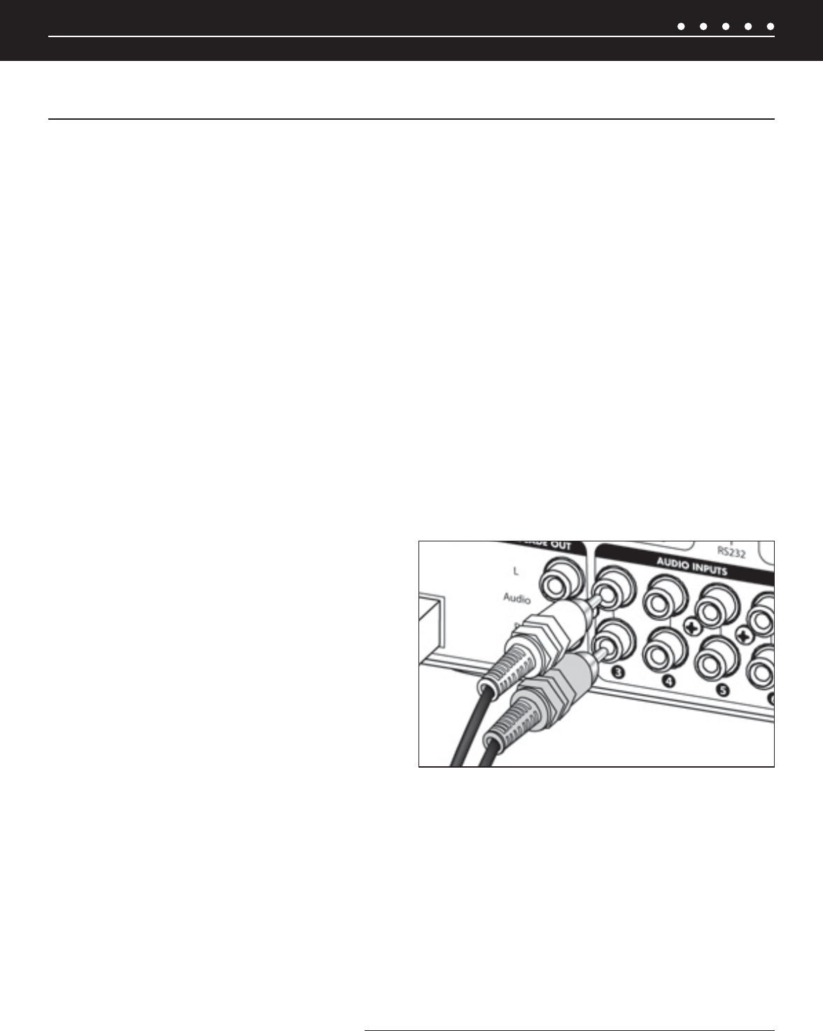
CONNECT THE AUDIO SOURCE DEVICES
Connect each source’s audio output cables to the corresponding
audio input connection of the ZR-6 MultiZone Receiver. When
making the connections, be sure that the audio cable’s two RCA
connectors are fully seated and that the proper color-code is
followed (white=left channel; red=right channel). The audio inputs
are labeled 2, 3, 4, 5 and 6 (Input 1 is the built-in AM/FM tuner).
When an iPod is used with the system, it is Input 2 and the analog
Source 2 input jacks become cascade audio outputs for the iPod
(Figure 11).
CONNECT THE iPod
Only USB host devices are supported fully. Other iPod types may not receive power and may not be charged while connected to the ZR-6
MultiZone Receiver. See the current iPod compatibility Matrix at www.nilesaudio.com. The supplied iPod connecting cable is labeled “iPod”
and “System”. Be certain to connect the cable in its proper orientation with the “System” label facing up when connected to the ZR-6
MultiZone Receiver and the “iPod” label facing the front of the iPod. The cable will only connect one way. Forcing it may cause damage.
CONNECT THE PAGING INPUT
The Page input on the rear panel of the ZR-6 MultiZone Receiver provides a connection for the paging out signal of telephone or intercom
systems for voice paging through the speakers in the listening zones (
Figure 10).
SYSTEM INSTALLATION
ZR-6 MULTIZONE RECEIVER SYSTEM INSTALLATION
Figure 11. Proper connection of audio input cables
(CONTINUED ON NEXT PAGE)


