12
McIntosh A/V Control Center
To AC Outlet
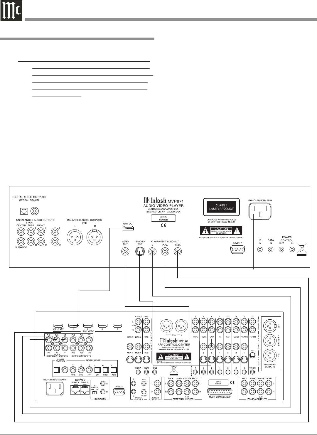
How to Connect Video and AC Power
How to Connect Video and AC Power
1. Connect component video cables between the MVP871
and the McIntosh A/V Control Center as follows:
Note: The MVP871’s default setting for the Component
Video Output Signal is Progressive Scan. Before
connecting AC Power to the MVP871, please refer
to the Setup Section entitled “Component Video
Out” on page 27 of this Owner’s Manual for im-
portant information.
A. Connect a cable from the MVP871 Y OUTPUT to
the Component Video Input of the McIntosh A/V
Control Center.
B. Connect a cable from the MVP871 P
B
/C
B
OUTPUT
to the P
B
Component Video Input of the McIntosh
A/V Control Center.
C. Connect a cable from the MVP871 P
R
/C
R
OUTPUT
to the P
R
Component Video Input of the McIntosh
A/V Control Center.
2. Connect a cable from the OUT connector on the
MVP871 to the 4 connector on the McIntosh A/V
Control Center.
To provide a Video Signal for making a recording, for
viewing in Zone B and/or a TV/Monitor without either a
Component Video Input and/or Input then connect as fol
-
lows:
3. Optionally, connect a S-Video Cable from the MVP871
S-VIDEO OUT jack to the DVD S-Video input jack on
the McIntosh A/V Control Center.
4. Optionally, connect a Video Cable from the MVP871
VIDEO OUT jack to the DVD Video input jack on the
McIntosh A/V Control Center
5. Connect the MVP871 power cord to a live AC outlet.
Note: When AC Power is initially applied to the MVP871
the unit will momentarily switch On and then go
into the Standby Mode.


