iCOM
Controls Training and Service Manual
The Basics for Cooling Unit Placement:
Installation instructions are found in the product manuals for the Cooling units.
Networking setup should include these additional factors for planning.
• Locations of heat loads in conditioned space.
• Air distribution for cooling.
• Number of operating units versus standby.
The Basics for Hardware:
Multi-unit networking requires the following hardware:
Minimum Network Switch Requirements:
• IEEE 802.3, IEEE 802.3u
• 10/100 Mbps speed
• Multiple RJ-45 ports – one shared RJ45 uplink
CAT 5 patch cables (straight through) in the proper lengths not to exceed
150 ft. maximum length each. One for each board and display added into
the iCOM network. Cable management will apply.
The Basic for Programming:
An IP address number will be used to identify each receiver/ sender of information.
(See Computer and Network Terms in Training and Service Manual)
The iCOM Network is a Class C Private Network and will use the 192.168.254.xxx
series of static IP address. This has nothing to do with the local building or owner
network. The iCOM Network may only be attached to these networks through a
WEB Card or 485 Card using the Liebert Intellislot.
A series of basic rules must be followed to connect and program the units for this
private iCOM Network. See the following rules.
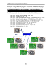
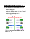
1. Small Displays are CAN connections only, programming of single unit
parameters is required.
2. Small Displays CANNOT look at or program other iCOM Network functions.
3. Small Displays may be networked with a CAT 5 crossover cable (2 units).
4. All Large Displays and Control Boards will use a CAT 5 or greater straight
through (patch) cables to connect to the switch.
5. One large Display (Wall Mount) with a separate power adapter may be used
with multiple units (Control Boards and Small Displays) through the network
switch.
42


