


iCOM
Control Training and Service Manual
117
The triacs that Liebert uses are standard in the industry and are rated at a 2-amp
capacity. You can check these devices for proper operation while they are
connected in the circuit. If the load is removed from the device, you can get a
false reading from the meter. This is because the voltage potential is present and
is detected by the meter. When the load is applied to the device, the potential is
not detected by the meter. To test a triac for proper operation, energize the circuit
and connect the load.
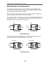
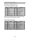
Heat Si
B
Termina
Front View Left Side View
Front and Left Side Views of the Triac
As your view the triac from the front, the terminals are numbered as follows:
Terminal
nk
ody
ls
Connection
Left #2 Connects to the Load
Middle #1 Connects to the Transformer power
Right G(ate) Connects to the Opto-Isolator
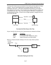
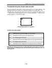
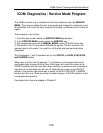
Below is a simple schematic drawing for the triac using Liebert symbols.
Schematic Drawing for the Triac
O
24 VAC
Transformer
Power
Load
Device
Opto
1
2
6
G
1
2
Triac
4