


iCOM
Control Training and Service Manual
111
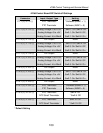
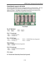
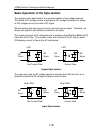
Fuse Board Layout: All Units
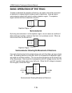
This section deals with the seven (7) plug connectors on the fuse board. The fuse
board is supplied on all systems with iCOM and is located in the low voltage
section of the unit. The tables in this section show all of the connections and
reference points for signal flow through these connectors.
Fuse Board
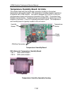
P4: 24 VAC Power
P4-1: Fuse 1 P4-3: Fuse 3
P4-2: Fuse 2 P4-4: Fuse 4
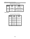
P24: T1 Transformer
P24-1: 24 VAC Gnd (T1)
P24-2: 24 VAC (T1)
P41: 24 VAC Power
P41-1: 24 VAC Gnd (T1) P41-3: 24 VAC Gnd (not unit ground)
P41-2: 24 VAC (T1) P41-4: 24 VAC
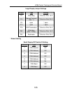
P42: Intelleslot
P42-1: 24 VAC Gnd (not unit ground)
P42-2: 24 VAC
P43: T6 Transformer
P43-1: 24 VAC Gnd (not unit ground)
P43-2: 24 VAC
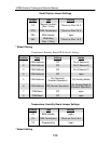
P44: Jumper
E1: Transformer Secondary Ground (unit ground)