


iCOM
Control Training and Service Manual
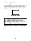
2. If the programming is correct and the output opto-isolator is functioning
properly but the load device is not activated the next step is to check the
triac and hard wiring to the load device. Verify that 24 VAC is being applied
to Pin 1 of the triac, place the VOM leads between Pin 1 and the proper
transformer ground connection. If 24 VAC is not present at Pin 1 of the
triac backtrack the circuit to the proper secondary hot of the control
transformer.
If 24 VAC is present perform the following:
Select the appropriate diagnostics function from the control menu; use the training
and service manual for reference. During the TEST OUTPUTS function the green
LED on the microprocessor should light. If the LED lights check the hardware from
the plug to the load device. If the LED does not light run the TEST CONTROL
BOARD diagnostics function. If board failure is displayed contact your local sales
office.
Note: Triacs are current limiting devices; therefore the load device must be
connected to obtain valid voltage readings when doing VOM checks and circuit
troubleshooting. Repair or replace any missing or defective components in the
circuit.
Mechanical Problems: If the failure of the load device to activate is determined
to be mechanical in nature consult the appropriate Liebert system operation and
maintenance, reference the individual component manufacturers literature or
contact your local Liebert representative.
125