


iCOM
Controls Training and Service Manual
120
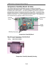
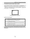
Troubleshooting the Input Opto-Isolator
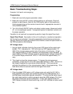
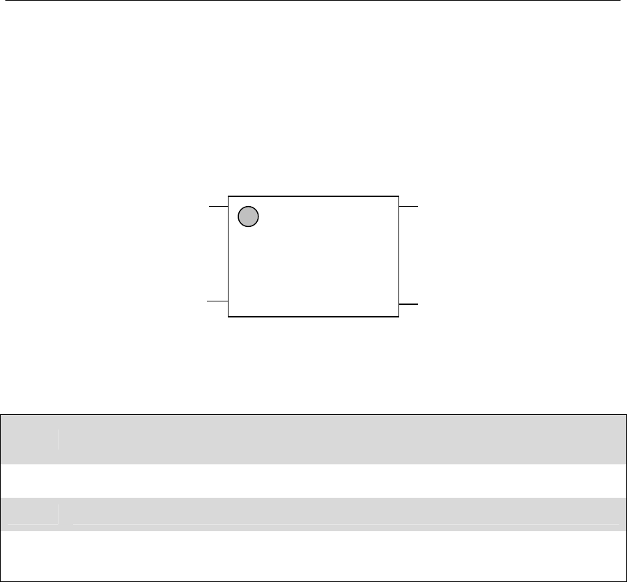
The opto-isolator IC chips used in these circuits are the H11AA (input) devices. The
pin location for component checks on the input opto. The indented circle in the
upper left hand corner of this chip indicates the location of Pin 1. Note that the
number sequence is in a "U" format: down 1 and 2 on the left and up 3 and 4 on
the right.
Input Opto-Isolator Pin Location
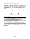
INPUT VOLTAGE CHECK
Pin 1
Receives the AC source voltage (This voltage is 24 VAC prior to the Opto
and is about 1.2 VAC at the opto).
Pin 2 Completes the AC source to the neutral and or safety ground.
Pin 3 Completes the DC source to the digital ground.
Pin 4
Receives the DC voltage source from the microprocessor (This voltage
level is 3.3 VDC when not activated and is 0 VDC when activated.)
Note that all AC source checks are referenced to the associated transformer
neutral and/or the safety ground, and that the DC source reference is to -V or
digital ground.
4
32
1