


23
INSTALLATION
ENGLISH
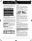
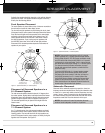
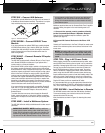
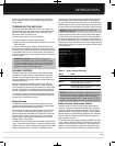
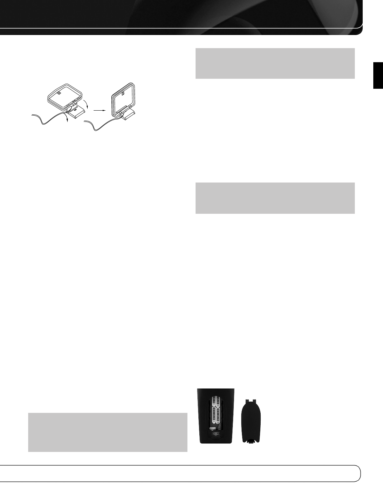
STEP SIX – Connect AM Antenna
Assemble the included AM antenna (see Figure 18) and connect it
to the AM and Ground antenna terminals. The antenna is not polar-
ized, and either lead may be connected to either terminal.
Figure 18 – AM Antenna Assembly
STEP SEVEN – Connect SIRIUS Tuner
Module
If you have purchased an optional SIRIUS tuner module designed
for SIRIUS-Ready devices, plug it into the SIRIUS jack. Purchase
a subscription and activate the module, following the instructions
posted at www.sirius.com. Place the module within view of a
south-facing window.
STEP EIGHT – Connect Remote IR Inputs
and Outputs
The AVR 2600 is equipped with a Remote IR Input, a Zone 2 Input
and a Remote IR Output to facilitate use of your system with a
remote control in a variety of situations.
When the AVR 2600 is placed inside a cabinet or facing away from
the listener, connect an external IR receiver, such as the optional
Harman Kardon HE 1000, to the Remote IR Input jack. For multizone
operation, connect an optional IR receiver, keypad or other control
device to the Zone 2 IR Input for remote control of the AVR 2600
(and any sources connected to the AVR’s Remote IR Output) from
the remote zone. Signals transmitted through the Zone 2 IR Input will
control source selection and volume for the main or remote zone,
depending on the setting of the remote’s Zone Selector. If a source
device is shared with the main listening area, any control commands
issued to that source will also affect the main room.
If any source devices are equipped with a compatible Remote IR
Input, use a 1/8-inch mini-plug interconnect cable (not included)
to connect the AVR’s Remote IR Output to the source device’s
Remote IR Input.
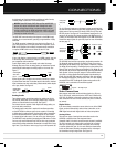
To control more than one source device through the Remote IR
Output, connect all sources in “daisy chain” fashion, connecting
each device’s IR output to the next device’s IR input, starting with
the AVR.
STEP NINE – Install a Multizone System
The AVR 2600 offers the ability to distribute audio to other areas in
your home.
IMPORTANT SAFETY NOTE: Installing a multizone
system typically requires running cables inside walls. Always
comply with the appropriate safety codes when installing con-
cealed wiring, particularly all applicable state and local build-
ing codes and the NEC (National Electrical Code). Failure to do
so may present a safety hazard. If you have any doubt about
your ability to work with electrical and telecommunications
wiring, hire a licensed electrician or custom installer to install
the multizone system.
Multizone operation takes over the Surround Back/Zone 2 amplifier
channels, limiting the system in the main listening room to 5.1
channels.
1. Connect the remote room’s speakers directly
to the Surround Back/Zone 2 Speaker Outputs.
Reassign the Surround Back amplifier channels to power the
speakers (see page 42).
2. Connect IR Control Devices to the Zone 2 IR
Input
Connect an IR control device to the Zone 2 IR Input for remote-room
control of the multizone system, source devices and volume in the
remote zone.
NOTE: Only analog audio sources are available to the multi-
zone system. For digital sources, make a second, analog audio
connection. The Bridge III source is available to the multizone
system.
STEP TEN – Plug in AC Power Cords
Before plugging the AVR into an unswitched electrical outlet, make
sure the Main Power Switch on the rear panel is off, to prevent the
possibility of damaging the AVR in case of a transient power surge.
You may plug one device that draws no more than 50 watts into
the AC Switched Accessory Outlet on the rear panel. Turn on the
device’s mechanical or master power switch, and that device will
power on any time the AVR 2600 is turned on (some devices may
require additional steps to power on from their standby mode). If the
device has a clock or must always be on (such as a cable set-top
box programmed to make recordings), do not plug it into this outlet.
Plug the AC Power cord into an unswitched AC outlet.
It is recommended that you copy the appropriate information from
the Table 2 worksheet to Table A5 in the appendix for future refer-
ence, in the event changes are made to the system components.
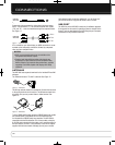
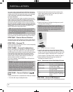
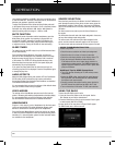
STEP ELEVEN – Insert Batteries in Remote
The AVR 2600 remote control uses four AAA batteries (included).
To remove the battery cover located on the back of the remote,
squeeze the tab and lift the cover.
Insert the batteries as shown in Figure 19, observing the correct
polarity.
Figure 19 – Remote Battery Compartment
0142CSK - HK AVR 2600 OM Inlay_ENG_v2.qxp:HKP1477AVR245om.v2.qxd 26/05/09 10:36 Side 23