


22
INSTALLATION
The Bridge III Insert iPod Model
NANO iPod nano, 1st and 2nd generation
5G (VIDEO 60GB) iPod, 5th generation (60GB, 80GB),
and iPod classic (160GB)
5G (VIDEO 30GB) iPod, 5th generation (30GB), and
iPod classic (80GB)
13 iPod nano, 3rd and 4th generation
12, 14 iPod touch – install large bumper;
iPhone or iPhone 3G – install small
bumper
You are now ready to begin installing the AVR. Before beginning to
connect the various components to the receiver, turn off all devices,
including the AVR 2600, and unplug their power cords.
Don’t plug
in any of the power cords until you have finished making
all of your connections.
The receiver generates heat. Select a location that leaves several
inches of space on all sides. Avoid completely enclosing the receiver
inside an unventilated cabinet. Place components on separate
shelves rather than stacking them directly on top of the receiver.
Never block the AVR’s ventilation slots on the top and side panels.
Doing so could cause the AVR to overheat, with potentially serious
consequences.
Some shelf surface finishes are delicate. Try to
select a location with a sturdy surface finish.
TIP: Label each cable before connecting it, to avoid mistakes.
Write a description of the cable on a blank adhesive label,
e.g., “DVD”, and fold the label around the cable about 6 inches
from the end to be plugged into the AVR.
Almost all of the following installation steps are optional, depending
on your system. Skip any step that does not apply to your system.
STEP ONE – Connect Source Devices
Leaving all AC power cords unplugged, connect the source devices
to the AVR using the audio and video inputs you assigned in Table 2.
STEP TWO – Connect TV
Connect the system-best video input on the TV to the corresponding
video monitor output on the AVR.
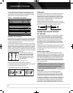
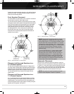
STEP THREE – Connect Loudspeakers
After you have placed your loudspeakers in the room as explained
on page 19, connect each speaker to its color-coded terminal on
the AVR. Maintain proper polarity by connecting the negative terminal
on the speaker (usually colored black) to the negative terminal
on the AVR (also colored black); and the positive terminal on the
speaker (usually red) to the positive terminal on the AVR (color
varies by channel; see Table 1 on page 16).
If you have a subwoofer, connect its line-level or LFE input to the
purple Subwoofer Output.
NOTE: If the subwoofer only has speaker-level inputs, after
you have configured the AVR using EzSet/EQ technology as
described on page 25, connect the subwoofer’s left and right
speaker input terminals to the AVR’s Front Left and Front Right
Speaker Outputs, then connect the front left and right main
speakers to the subwoofer’s left and right speaker output
terminals. Consult the owner’s manual for the subwoofer for
specific installation instructions.
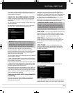
STEP FOUR – Connect Optional
Dock
To enjoy content stored on a compatible iPod or iPhone (not included):
1. Turn off the AVR, using its Standby/On Switch.
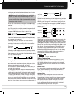
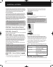
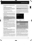
2. Holding the cable with the wider part of the connector at the
bottom, gently squeeze the tabs on each side as you insert it
into the connector on the rear panel.
See Figure 16.
Figure 16 – The Bridge III Connector
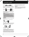
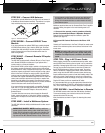
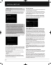
3. Place the black insert in The Bridge III, making sure to push it
all the way down. See Figure 17.
NOTE: Do not place an iPod or iPhone in The Bridge III
unless both the black insert and a dock adapter are installed.
Otherwise, the iPod or iPhone will not connect properly, and
both it and The Bridge III may sustain damage that is not
covered by the warranty.
Figure 17 – Docking an iPod or iPhone in The Bridge III
4. Locate the dock adapter that was included with your iPod or
iPhone, or select one of the included dock adapters by referring
to Table 3. If your iPod or iPhone does not appear in Table 3 and
did not include an adapter, contact Apple Inc. to purchase one.
Place the adapter in The Bridge III insert, as shown in Figure 17.
5. Remove the iPod or iPhone from any case, and dock it in
The Bridge III, as shown in Figure 17.
Table 3 – Select the Correct The Bridge III Insert
STEP FIVE – Connect FM Antenna
Connect the included FM antenna to the 75-ohm FM antenna terminal.
0142CSK - HK AVR 2600 OM Inlay_ENG_v2.qxp:HKP1477AVR245om.v2.qxd 26/05/09 10:36 Side 22