


AGILENT 35670A
Supplemental Operator’s Guide
17
Use the marker knob to read the amplitude at any measured frequency for Channel 1
in Trace A.
To set up the marker for Channel 2 in Trace B,
• Press the [Active Trace] hardkey.
• Press the [B] softkey (F2).
• Press the [Marker] hardkey.
• Toggle the [MARKER ON OFF] softkey (F1) until ON is highlighted.
The marker knob is now active for Trace B, which is Channel 2. To gain control of
the marker on Trace A again, make it the active trace as follows:
• Press the [Active Trace] hardkey.
• Press the [A] softkey (F1).
Coupled Markers
Markers on multiple traces can be coupled so that one marker will always track the
frequency specified in another trace. This makes comparisons of level differences
across channels simple. To set up coupled markers so that Trace B will follow the
marker frequency specified in Trace A, do the following:
• Press the [Active Trace] hardkey.
• Press the [A] softkey (F1).
• Press the [Marker] hardkey.
• Toggle the [COUPLED ON OFF] softkey (F1) until ON is highlighted.
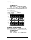
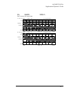
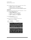
Move the knob to move the marker in Trace A. Notice that the marker in Trace B
moves to the same frequency.
Coupled Markers with Peak Tracking
Coupled markers can be further used to track a peak frequency in Trace A and
determine the response amplitude at the peak frequency in Trace B. To do this, leave
coupled markers on, as above, then set up peak tracking in Trace A as follows:
• Press the [Active Trace] hardkey.
• Press the [A] softkey (F1).
• Press the [Marker] hardkey.
• Toggle the [PEAK TRK ON OFF] softkey (F1) until ON is highlighted.
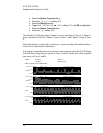
• Press the yellow [Start] hardkey.
Notice that the marker in Trace A moves to the peak value, whereas the marker in
Trace B moves to the same frequency as determined in Trace A.