


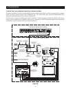
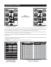
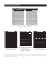
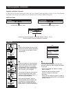
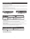
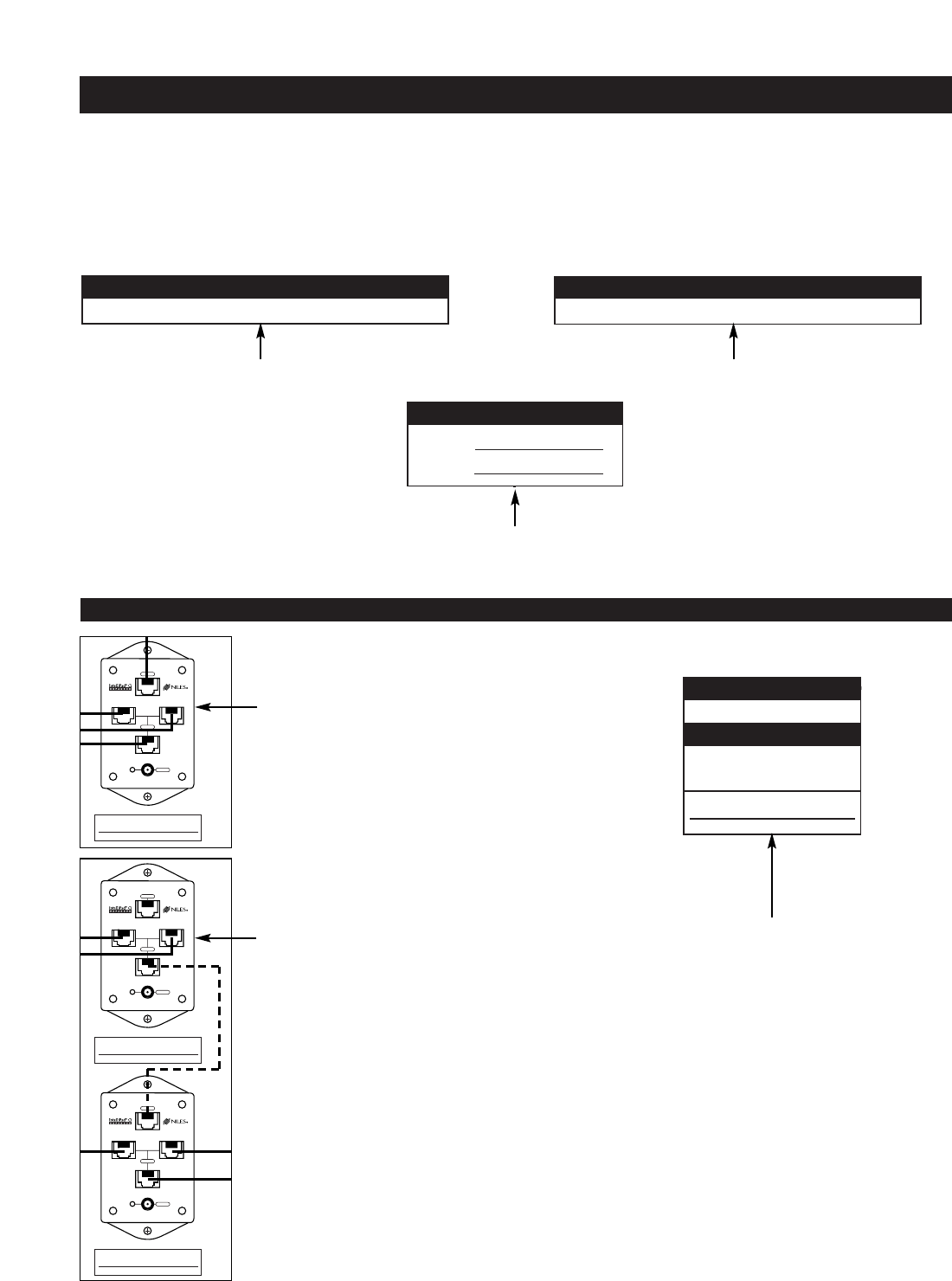
Expander Installation Schematic
If your system has zones that require more than one keypad, install expanders in those zones. The Expander
Schematic sheet (Figure 44) enables you to document each of those additional keypads.
Multi-Area Zone
51
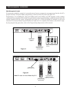
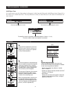
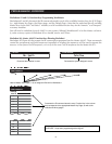
PROGRAMMING OVERVIEW
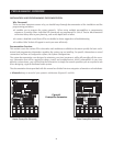
1
JOB TITLE
2
SYSTEM DESIGNER
Document the customer’s name. Document the system designer’s name.
Mr. Smith John Doe
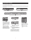
TO A4.6Ci
ZONE#
3
OUTPUT CONNECTION
The A4.6Ci to which the expander is connected (Master or Slaves 1, 2, or 3).
The zone number to which the expander is connected.
4
AREA SETUP
4A
Assign the first expander the same number
as the zone to which it connects, followed by
"A" (for example, the expander for Zone 6
would be #6-A).
4B
If a second expander is required because
the area needs more than three keypads,
it becomes Expander "B" (for example,
two expanders for Zone 6 would be #6-A
and #6-B). With a second expander, the
zone can have up to five keypads.
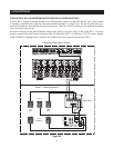
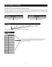
The top input of Expander (A) connects to
the A4.6Ci keypad input. With a single
expander connect keypads for Areas 1, 2,
and 3 to the remaining inputs.
When a second expander is required,
connect Expander (B) to the bottom input
of Expander (A). Connect keypads for
Areas 1 and 2 to Expander (A) and key-
pads for Areas 3, 4, and 5 to Expander (B).
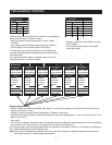
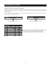
MASTER KEYPAD MODULE (CHOOSE ONE)
❏ SOLO
❏ SELECT
OPTIONAL ACCESSORY MODULES
❏ NUMERIC
❏ TRANSPORT
❏ IR SENSOR
AREA NAME
AREA 1
4C
Keypad Input Information:
If you have different keypads in the same zone,
document individually, which keypads are installed
in each area.
• Identify which Master Key Module is installed
(Solo
™
or Select
™
).
• Indicate any optional Accessory Module
(Numeric
™
, Transport
™
, or IR sensor).
• Area Name
Identify the area where the keypad is located (for
example, left side of bed for Area 1 and right side
of bed for Area 2).
Master
6
6A
6B
1
2
3
OUTPUT
POWER
INPUTS
EXPANDER #
6A
EXPANDER #
6A
1
2
3
OUTPUT
POWER
INPUTS
EXPANDER #
6A
1
2
3
OUTPUT
POWER
INPUTS
EXPANDER #
6B