Light Sensing
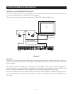
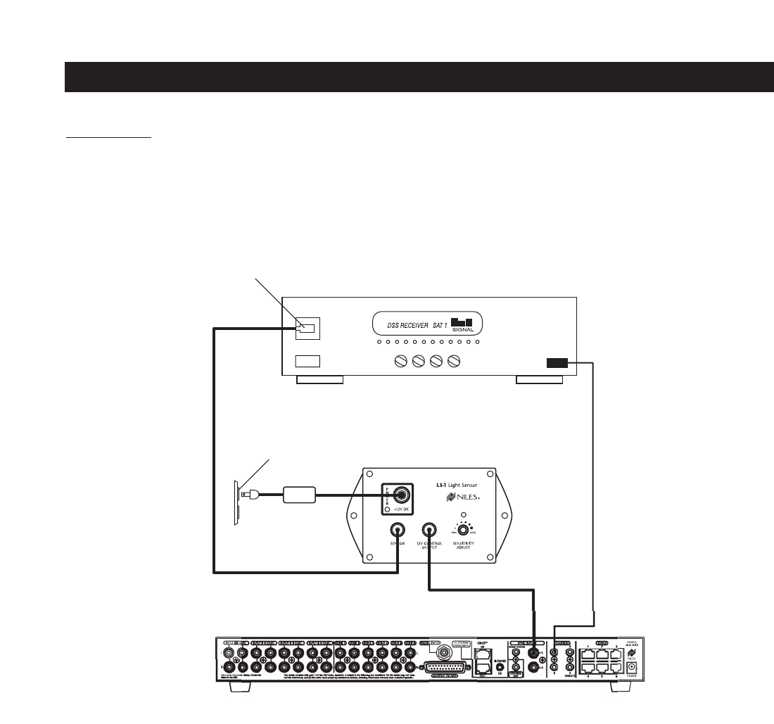
Using a light sensor (LS-1) to synchronize your components is usually your last choice, simply because the other
choices are more reliable. The Niles LS-1 Light Sensor can synchronize a component by sensing changes in light.
The 12V output of the LS-1 is then connected to the A4.6Ci’s sync input dedicated for that component. A mini-
plug to RCA adapter is required for this connection (see Connections for more information).
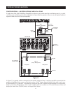
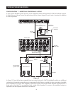
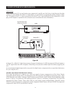
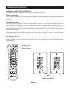
In Figure 20, a Niles LS-1 Light Sensor senses changes in brightness of a DSS’s front-panel LED and outputs a
12V DC signal when the LED is brightest. A blocking cover prevents ambient light from falsely triggering the
LS-1.
An unused optical digital output on the rear panel of a digital source component also can provide a light source
for sync using the LS-1.
SOURCE AND HOME THEATER SYNC STATUS
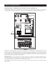
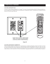
Sync status (the presence or absence of a valid sync signal) of source components and the Home Theater
associated with the Master A4.6Ci are displayed on the LEDs located in the hidden programming panel. These
LEDs illuminate only while a valid sync signal is being received by the A4.6Ci during normal operation mode.
Source 2, Source 3, and Source 4 LEDs represent Source 2, Source 3, and Source 4 respectively. The Tuner LED
represents the Home Theater. These status LEDs are used during system troubleshooting. Manually turning
ON/OFF synchronized source components and the integrated Home Theater will turn ON/OFF the respective
component’s status LED if synchronized correctly.
27
SOURCE-POWER SYNCHRONIZATION
Unswitched
AC Outlet
Power Supply
Niles LS-1
DSS
Light Sensing Probe
placed over an LED
Figure 20


