


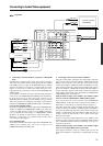
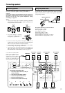

19
PRE
FRONT
SUB
SURR
R
GND
SURR
BACK/
ZONE 2
R
FRONT
SUB
SURR
SURR
BACK
R
R
DIGITAL
INPUT
DIGITAL
OUTPUT
OPT
OPT
2
1
2
3
4
1
2
1
3
COAX
AUDIO
VIDEO
S VIDEO
MONITOR
OUT
IN
IN
IN
IN
IN
ZONE 2
DVD
VIDEO 1
VIDEO 2
VIDEO 3
VIDEO 4
AUDIO
VIDEO
S VIDEO
COMPONENT
VIDEO
Y
P
B
P
R
OUTPUT
INPUT 1
Y
P
B
P
R
INPUT 2
Y
P
B
P
R
R
L
OUT
OUT
OUT
PHONO
O
L
CD
TAPE
L
O
IN
OUT
AM
FM
75
R
L
NNA
P
R
P
B
Y
: Signal flow
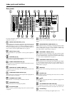
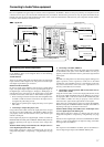
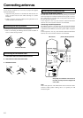
Connecting to Audio/Video equipment
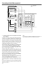
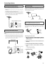
5. Connecting a television monitor or projector (MONITOR
OUT)
The DTR-8.3 is equipped with a simple Y/C separate circuit and
simple Y/C mixed circuit. Since both the signal from the S VIDEO
and VIDEO inputs are output to the MONITOR OUT S VIDEO
output, if the television or projector is equipped with an S video
input, it is unnecessary to connect the video connectors. If it is
equipped with only a video input, connect it to the MONITOR OUT
VIDEO output.
Using an RCA video cable, connect the video input jack (composite)
of the device to the MONITOR OUT VIDEO jack of the DTR-8.3.
Or if the device has an S video input jack, connect it to the
MONITOR OUT S VIDEO jack of the DTR-8.3 using an S video
cable. Or if the device has component video inputs, connect them to
the bank of COMPONENT VIDEO OUTPUT jacks on the DTR-8.3.
For USA and Canadian models:
Note that the OSD Menu data will be output to the MONITOR OUT
VIDEO, S VIDEO and COMPONENT VIDEO jacks. When you
connect any OSD-specific monitor TV to the VIDEO connectors,
you can disable the OSD output to COMPONENT VIDEO
OUTPUT. To disable the OSD output, select Setup Menu →
Preference → OSD Setup → Component Video, and then select
“Not Activated” (See page 63).
For Australian model:
Note that the OSD Menu data will be output to the MONITOR OUT
VIDEO and S VIDEO jacks, and will not output to the
COMPONENT VIDEO OUTPUT jack.
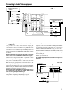
6. VCR (VIDEO 1)
Analog audio
output
S Video output
Video output
S Video input
Video input
Analog audio
input
R (red)
L (white)
R (red)
L (white)
5. TV monitor or projector
(MONITOR OUT)S Video input
Video input
Component video input
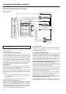
6. Connecting a video cassette recorder (VIDEO 1)
Using RCA video cables, connect the video output jack (composite)
of the video cassette recorder to the VIDEO 1 VIDEO IN jack of the
DTR-8.3 and connect the video input jack of the video cassette
recorder to the VIDEO 1 VIDEO OUT jack of the DTR-8.3. Or if the
video cassette recorder has S video input and output jacks, connect
them to the VIDEO 1 S VIDEO IN and OUT jacks of the DTR-8.3
using S video cables. Or if the video cassette recorder has component
video outputs, connect them to one of the banks of COMPONENT
VIDEO INPUT jacks on the DTR-8.3.
With the initial settings of the DTR-8.3, the VIDEO 1 input
source is set for the COMPONENT VIDEO INPUT 2 jacks.
If you connect the video cassette recorder to the COMPONENT
VIDEO INPUT 1 jacks, this must be changed at Setup Menu →
Input Setup → Video Setup → Component Video (see page 51).
Using RCA audio cable, connect the audio output jacks of the video
cassette recorder to the VIDEO 1 AUDIO IN jacks of the DTR-8.3
and connect the audio input jacks of the video cassette recorder to the
VIDEO 1 AUDIO OUT jacks of the DTR-8.3. Make sure that you
properly connect the left channels to the L jacks and the right
channels to the R jacks.
If you are connecting a digital output device to the VIDEO 1 jack
instead of a VCR, connect it to either the DIGITAL INPUT COAX
jack or DIGITAL INPUT OPT jack depending on the type of
connector on the device.
With the initial settings of the DTR-8.3, the VIDEO 1 input
source is set for digital input at the COAX 2 jack.
If the digital connection is made at a different jack, this must be
changed at Setup Menu → Input Setup → Digital Setup (see page
49).