


13
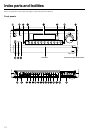
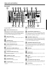
Index parts and facilities
Rear panels
SURR
BACK/
ZONE 2
SPEAKERS
AUDIO
VIDEO
S VIDEO
MONITOR
OUT
IN
IN
IN
IN
IN
ZONE 2
DVD
VIDEO 1
VIDEO 2
VIDEO 3
VIDEO 4
AUDIO
VIDEO
S VIDEO
COMPONENT
VIDEO
Y
P
B
PR
OUTPUT
INPUT 1
Y
P
B
PR
INPUT 2
Y
P
B
PR
FRONT SPEAKERS
L
R
R
SURR SPEAKERS
CENTER
SPEAKER
R
L
R
L
OUT
OUT
OUT
PHONO
PRE OUT
FRONT
SUB
SURR
R
L
AUDIO
R
L
CD
TAPE
R
L
AUDIO
GND
SURR
BACK/
ZONE 2
IN
OUT
R
L
MULTI
CH
INPUT
FRONT
SUB
SURR
SURR
BACK
CENTER
R
L
R
L
AM
FM
75
DIGITAL
INPUT
DIGITAL
OUTPUT
OPT
OPT
2
1
2
3
4
1
2
R
L
1
3
COAX
I
R
IN
ZONE 2
REMOTE
CONTROL
A
B
RS232
OUT
12
V
TRIGGER OUT
AC
120
V 60
Hz
SWITCHED
TOTAL 120W 1A MAX.
AC OUTLETS
AV RECEIVER
MODEL NO.
DTR
-
8.3
RATING
:
AC 120
V 60
Hz 8.4
A
AC
INLET
CENTER
ANTENNA
4 OHMS MIN. OR
6 OHMS MIN.
/SPEAKER
CAUTION
:
SPEAKER
IMPEDANCE
SEE INSTRUCTION
MANUAL FOR
CORRECT SETTINGS.
ETHERNET
[NET-TUNE]
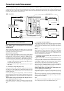
For more information regarding connection procedures, see pages
indicated in brackets [ ].
DIGITAL INPUT/OUTPUT [17-21]
These jacks are for connecting components with digital input and
output capabilities. To connect a CD player, see page 17; to connect an
MD or CD recorder, see page 17; to connect a DAT deck, see page 17;
to connect a DVD player, see page 18; to connect a DVD recorder, see
page 20; and to connect a digital satellite tuner, see page 21.
PRE OUT [23, 26, 29]
To use the DTR-8.3 as a preamplifier, connect a power amplifier to
this jack.
ANTENNA [24, 25]
These jacks are for connecting the FM indoor antenna and AM loop
antenna that are supplied with the DTR-8.3.
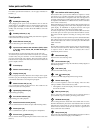
ZONE2 AUDIO/VIDEO OUT [26]
These jacks are for connecting the components that will be used in
the remote zone (Zone 2).
MONITOR OUT VIDEO/S VIDEO [19]
These jacks are for connecting to the video input jacks on television
monitors or projectors.
COMPONENT VIDEO OUTPUT [19]
These jacks are for connecting to the component video input jacks on
television monitors or projectors.
ETHERNET (NET-TUNE)
This connector is for connecting to an Ethernet network.
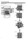
SPEAKERS [23, 26]
These terminals are for connecting the speakers.
AC OUTLETS [28]
This AC outlet is provided to plug in the power cord from another
component.
MULTI CH INPUT [29]
This connector is for connecting components with a multi-channel
output.
PHONO/CD/TAPE AUDIO IN/OUT [17]
These connectors are for connecting to the audio input and output
jacks on audio components. To connect a turntable, see page 17; to
connect a CD player, see page 17; and to connect a cassette tape
deck, MD recorder, or CD recorder, see page 17.
DVD/VIDEO1-4 IN/OUT [18-21]
These connectors are for connecting to the video input and output
jacks on video components. To connect a DVD player, see page 18;
to connect a DVD recorder, see page 20; to connect a VCR, see page
19; and to connect a Satellite tuner, see page 21.
COMPONENT VIDEO INPUT1/2 [18-20]
These connectors are for connecting to the component video outputs
of video components that have them. To connect a DVD player, see
page 18; to connect a DVD recorder, see page 20; and to connect a
Satellite tuner, see page 21.
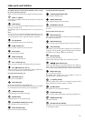
RS232 [28]
This connector is for connecting to the RS-232 port of an external
device.
IR IN/OUT [27]
These connectors are for connecting the remote sensor of a multi-
room kit (sold separately).
[28]
This jack is for connecting other Onkyo components equipped with
the same terminal.
12V TRIGGER OUT ZONE 2 A/B [29]
These connectors are used to connect to the 12V TRIGGER IN
terminal of a component in the remote zone (Zone 2) if one has one.
AC INLETS [7]
This connector is for connecting the supplied power cord.