


18
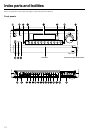
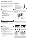
Connecting to Audio/Video equipment
PR
FRONT
SUB
SURR
R
GND
SURR
BACK/
ZONE 2
R
FRONT
SUB
SURR
SURR
BACK
R
R
DIGITAL
INPUT
DIGITAL
OUTPUT
OPT
OPT
2
1
2
3
4
1
2
1
3
COAX
AUDIO
VIDEO
S VIDEO
MONITOR
OUT
IN
IN
IN
IN
IN
ZONE 2
DVD
VIDEO 1
VIDEO 2
VIDEO 3
VIDEO 4
AUDIO
VIDEO
S VIDEO
COMPONENT
VIDEO
Y
P
B
P
R
OUTPUT
INPUT 1
Y
P
B
P
R
INPUT 2
Y
P
B
P
R
R
L
OUT
OUT
OUT
PHONO
UDIO
L
CD
TAPE
L
UDIO
IN
OUT
AM
FM
75
R
L
TENNA
P
R
P
B
Y
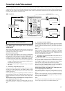
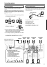
: Signal flow
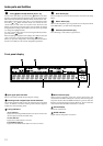
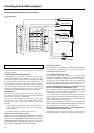
Connecting a DVD Player with 5.1-Channel Output
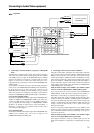
Connecting your video components
Below is an example of how you can connect your video components
to the DTR-8.3. Refer to the diagram above for the following
connection examples.
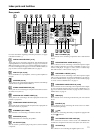
COMPONENT VIDEO INPUT/OUTPUT
For DVD players or other devices that have component video
connectors, the DTR-8.3 has two banks of component video input
connectors (Y, P
B, PR) for direct component video input. The DTR-
8.3 also has one bank of component video output connectors for
direct component video output to the matrix decoder of a television,
projector, or other display device. By sending the pure component
video signal directly, the signal forgoes the extra processing that
normally would degrade the image. The result is vastly increased
image quality, with incredibly lifelike colors and crisp detail.
VIDEO IN/OUT
These are the video inputs and outputs. On the rear panel, there are
five video inputs and two video outputs and each one includes both
composite video and S video configurations.
Connect VCRs, VTRs, LD players, DVD players, and other video
components to the video inputs. Connect VCRs, VTRs, and other
recording components to the video outputs to make video
recordings.
• When connecting a VCR or other video component, make sure
you connect its audio and video leads to the same bank (e.g.,
both to VIDEO 3).
• The VIDEO 5 inputs are located on the front panel.
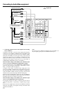
The flow of the video signals is as follows:
Signals that comes in from VIDEO and S VIDEO INPUT are output to
VIDEO, S VIDEO and COMPONENT VIDEO. However, signals
that comes in from COMPONENT VIDEO INPUT are only output to
COMPONENT VIDEO OUTPUT. When connecting a video player
to the COMPONENT VIDEO INPUT jacks, be sure to connect your
television to the COMPONENT VIDEO OUTPUT jacks.
For Australian model:
Signals that comes in from VIDEO and S VIDEO INPUT are output
to VIDEO and S VIDEO. Those signals are not output to
COMPONENT VIDEO OUTPUT.
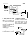
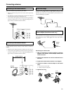
4. Connecting a DVD player (DVD)
Using an RCA video cable, connect the video output jack
(composite) of the DVD or LD player to the DVD VIDEO IN jack of
the DTR-8.3. Or if the DVD or LD player has an S video output jack,
connect it to the DVD S VIDEO IN jack with an S video cable. Or if
the device has component video outputs, connect them to one of the
banks of COMPONENT VIDEO INPUT jacks on the DTR-8.3.
With the initial settings of the DTR-8.3, the DVD input source is
set for the COMPONENT VIDEO INPUT 1 jacks.
If you connect the DVD or LD player to the COMPONENT VIDEO
INPUT 2 jacks, this must be changed at Setup Menu → Input Setup
→ Video Setup → Component Video (see page 51).
Using an RCA audio connection cable, connect the audio output
jacks of the DVD or LD player to the DVD AUDIO IN jacks of the
DTR-8.3. Make sure that you properly connect the left channel to the
L jack and the right channel to the R jack.
If the device has a digital output, connect it to either the DIGITAL
INPUT COAX jack or DIGITAL INPUT OPT jack of the DTR-8.3
depending on the type of connector on the DVD player.
With the initial settings of the DTR-8.3, the DVD input source is
set for digital input at the COAX 1 jack.
If the digital connection is made at a different jack, this must be
changed at Setup Menu → Input Setup → Digital Setup (see page 49).
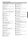
Analog audio output
Digital audio output (coaxial)
Video output
S Video output
4. DVD player (DVD)
Component video output
R (red)
L (white)