


28
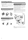
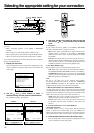
Miscellaneous Connections
The terminal on the DTR-6.4/5.4 is for connecting other
Integra/Onkyo components equipped with the same terminal.
When a component is connected to the terminal, it can be operated
by the remote controller supplied with the DTR-6.4/5.4. In addition,
when you connect a component to the terminal, you can also
perform the system operations given below.
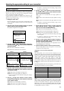
Power on/ready function
When the DTR-6.4/5.4 is in the standby state, if an -connected
component is turned on, the DTR-6.4/5.4 also turns on and the input
source selected at the DTR-6.4/5.4 automatically switches to that
component.
Be aware that this function will not work if the power cord for the
-connected component is connected to the AC OUTLET on the
DTR-6.4/5.4, or if the DTR-6.4/5.4 has already been turned on.
Direct change function
When the play button is pressed at an -connected component,
the input source selected at the DTR-6.4/5.4 automatically changes
to that component.
Power off function
When the DTR-6.4/5.4 is placed in the standby state, all -
connected components are also automatically put into the standby
state.
Also, if you press the On button on the DTR-6.4/5.4 remote
controller while the DTR-6.4/5.4 is turned on, all -connected
components (DVD players, CD players, MD recorders, tuners, etc.)
are also turned on.
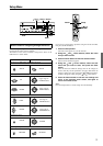
Dimmer function
The Dimmer function (display brightness adjustment) of the DTR-
6.4/5.4 can be used to synchronize the display brightness on the
connected device using the connection.
Caution:
If an MD recorder is connected to the TAPE jack on the DTR-6.4/
5.4, switch the Input Selector from TAPE to MD (see page 35).
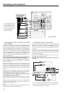
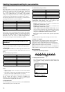
To connect components using the terminal, simply connect a
remote control cable from this terminal to the terminal of
the other component. An remote control cable with a 1/8-inch
(3.5-mm) miniature two-conductor plug comes with every cassette
tape deck, compact disc player, MD recorder, and DVD player that
has an terminal.
• When performing operations with -connected components
using the system, do not use the remote zone (Zone 2) .
• For remote control operation, the audio connection cables
must also be connected.
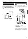
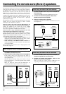
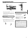
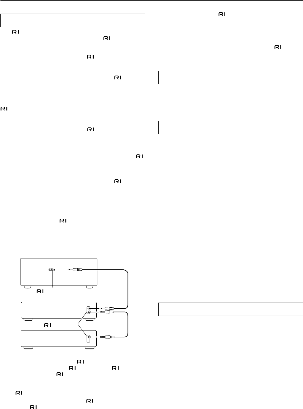
Connections for remote control
DTR-6.4/5.4
connector
Ex: Integra/Onkyo
CD player
Ex: Onkyo cassette tape
deck
connector
• If a component has two terminals, you can use either one to
connect to the DTR-6.4/5.4. The other one can be used to daisy
chain with another component.
• With Integra/Onkyo DVD players, you can enter the pre-
program code so that you can operate the DVD player directly
with the remote controller without connecting the terminals
(see pages 66 and 67).
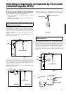
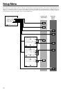
The RS232 port is to be used in conjunction with an external
controller to control the operation of the DTR-6.4/5.4 by using an
external device.
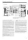
A-BUS is a simple, efficient, elegant audio distribution system. The
wiring installation time is significantly reduced as only a single
CAT-5 wire is run to each location. A-BUS is easy to use, reliable,
affordable, and most of all, far better sounding than conventional
autoformer based volume controls.
ZONE 2 OUT: Use a CAT-5 (eight conductor twisted) cable to
connect directly from the receiver’s A-BUS RJ45 Hub to an A-BUS
keypad.
Warning:
DO NOT connect A-BUS outputs to any computer or network
connections (i.e. ethernet). It will cause damage to the computer or
network components as 24-volt power runs on this same cable to
power the amplifier stages of the amplifier module.
IR OUT: Another feature of the A-BUS system is the ability to
control source equipment in another room where the A-BUS
module is installed. If you wish to control another source from the
receiver at the A-BUS keypad by remote control, connect A-BUS or
another brands' IR emitter on the receiver's 40 k terminal. Then
place the emitter on the remote receiver on the front panel.
Typically, the emitter will work when you connect with a 40 K
connector. If it does not work, try a 56 K connector.
DC IN: Connect A-BUS power supply. Do not use any other AC
Adapter on this connector as it may cause severe damage to the receiver.
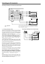
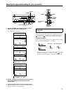
12V TRIGGER OUT A/B
These terminals are provided so that you can use the operation of
the DTR-6.4/5.4 control the operation of another externally
connected device. Connect the component to this 1/8-inch mini-jack
terminal and when the set input source is selected, the device will
turn on. Set the 12V TRIGGER terminal using the Setup menu:
Input setup → 12V trigger (see page 34).
12V TRIGGER OUT ZONE 2
When the DTR-6.4/5.4 is in the ZONE 2 mode, this terminal
outputs at 12 V/100 mA.
RS232
A-BUS
12V TRIGGER OUT