


11
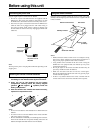
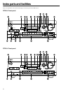
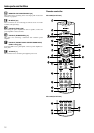
Index parts and facilities
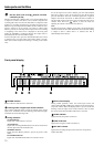
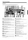
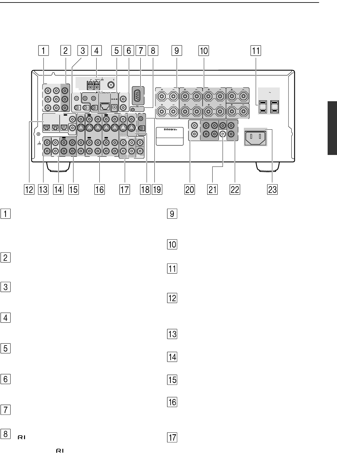
Rear panel
INPUT 1INPUT 2
OUTPUT
COMPONENT VIDEO
Y
IN
IN
IN
IN
FRONT
SURR
CENTER
SUB
WOOFER
VIDEO 2
VIDEO 1
VIDEO 2
DVD
MONITOR
OUT
DVD
TAPE
L
R
VIDEO 3
VIDEO 1
V
VIDEO 3
IN
IN
IN
OUT
IN
IN
OUTOUT
OUTOUTOUT
S
FRONT
SPEAKERS
ZONE
2
SPEAKERS
SURROUND
SPEAKERS
CENTER
SPEAKER
R
L
R
L
ANTENNA
FM
75
AM
AC OUTLETS
CAUTION: SPEAKER IMPEDANCE
6 OHMS MIN. /SPEAKER
IN
RS232
IR
MODEL NO.
DTR
-
6.4
AV RECEIVER
AC
INLET
AC
120
V 60
Hz
SWITCHED
TOTAL 120W 1A MAX.
IR OUT
56K
A
40K
B
ZONE 2
OUT
DC IN
24V 1A
L
R
ZONE 2
LINE OUT
ZONE 2
OPTICAL
1
2
OPTICAL
IN
OUT
SURROUND
BACK
SPEAKER
12 V
TRIGGER
OUT
A
B
REMOTE
CONTROL
IN
COAXIAL
IN
COAXIAL
DIGITAL
CD
L
R
GND
PHONO
FRONT SURR CENTER SURR BACK
(SB)
ZONE 2
SUB
WOOFER
PRE OUT
R
L
R
L
PR
PB
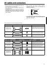
This illustration shows the DTR-6.4 shipped to the North American area. The number and
shape of the terminals may be different depending on the model and shipping area.
COMPONENT VIDEO INPUT 1/2 [19-22]
These connectors are for connecting to the component video
outputs of video components that have them. To connect a DVD
player, see page 20; to connect a DVD recorder, see page 22; and to
connect a Satellite tuner, see page 21.
COMPONENT VIDEO OUTPUT [19]
These jacks are for connecting to the component video input jacks
on television monitors or projectors.
12V TRIGGER OUT A/B/ZONE 2 [28]
These connectors are used to connect to the 12V TRIGGER IN
terminal of a component in the remote zone (Zone 2) if one has one.
ANTENNA [24, 25]
These jacks are for connecting the FM indoor antenna and AM loop
antenna that are supplied with the DTR-6.4/5.4.
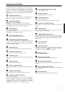
A-BUS Ready [28]
Use these terminals to connect the multi-home extension kit of the
A-BUS system.
ZONE 2 LINE OUT [26]
These jacks are for connecting the components that will be used in
the remote zone (Zone 2).
RS232 [28]
This connector is for connecting to the RS-232 port of an external device.
[28]
This jack is for connecting other Integra/Onkyo components
equipped with the same terminal. The audio connection cables
must also be connected.
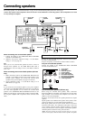
ZONE 2 SPEAKERS [26]
These terminals are for connecting the speakers that will be used in
the remote zone (Zone 2).
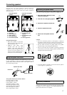
SPEAKERS [16]
These terminals are for connecting the speakers.
AC OUTLETS [23]
This AC outlet is provided to plug in the power cord from another
component.
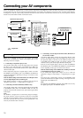
DIGITAL INPUT/OUTPUT [18, 20, 22]
These jacks are for connecting components with digital input and
output capabilities. For more information on connection between
the components, refer to each component's document.
PHONO IN L/R [18] (DTR-6.4 only)
These jacks are for connecting a turntable.
CD IN L/R [18]
These jacks are for connecting a CD player.
TAPE IN/OUT L/R [18]
These jacks are for connecting a cassette tape deck.
VIDEO 1-3 IN/OUT [21, 22]
These connectors are for connecting to the video input and output jacks
on video components. To connect a DVD recorder, see page 22; to
connect a VCR, see page 21; and to connect a Satellite tuner, see page 21.
DVD IN [20]
These jacks are for connecting a DVD player.