


19
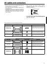
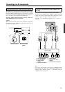
Connecting your AV components
INPUT 1INPUT 2
OUTPUT
COMPONENT VIDEO
Y
IN
IN
IN
IN
FRONT
SURR
CENTE
R
SUB
WOOFE
R
VIDEO 2
VIDEO 1
VIDEO 2
DVD
MONITOR
OUT
DVD
TAPE
L
R
VIDEO 3
VIDEO 1
V
VIDEO 3
IN
IN
IN
O
U
IN
IN
OUTOUT
OUTOUTOUT
S
ANTENNA
FM
75
AM
R
S
IR
IR OUT
56K
A
40K
B
ZONE 2
OUT
DC IN
24V 1A
L
R
ZONE 2
LINE OUT
ZONE 2
OPTICAL
1
2
OPTICAL
IN
OUT
12 V
TRIGGER
OUT
A
B
REMOTE
CONTROL
IN
COAXIAL
IN
COAXIAL
DIGITAL
CD
L
R
GND
PHONO
PR
PB
*
: Signal flow
(MONITOR OUT)
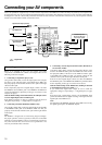
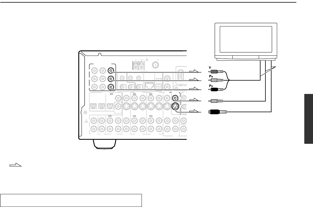
4. TV monitor or projector
Video input
S Video input
Component
video input
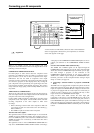
*You do not have to make all the connection shown on the illustration
above. For appropriate connection for your components, see “The flow
of the video signals” on this page.
Below is an example of how you can connect your video
components to the DTR-6.4/5.4. Refer to the diagram above for the
following connection examples.
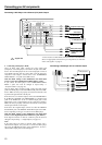
COMPONENT VIDEO INPUT/OUTPUT
For DVD players or other devices that have component video
connectors, the DTR-6.4/5.4 has two banks of component video
input connectors (Y, P
B, PR) for direct component video input.
DTR-6.4/5.4 also has one bank of component video output
connectors for direct component video output to the matrix decoder
of a television, projector, or other display device. By sending the
pure component video signal directly, the signal forgoes the extra
processing that normally would degrade the image. The result is
vastly increased image quality, with incredibly lifelike colors and
crisp detail.
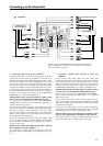
VIDEO IN/OUT, S VIDEO IN/OUT
These are the video inputs and outputs. On the rear panel, there are
four video inputs and two video outputs and each one includes both
composite video and S video configurations.
Connect VCRs, VTRs, LD players, DVD players, and other video
components to the video inputs. Connect VCRs, VTRs, and other
recording components to the video outputs to make video
recordings.
• When connecting a VCR or other video component, make sure
you connect its audio and video leads to the same bank (e.g.,
both to VIDEO 3).
• The VIDEO 4 inputs are located on the front panel.
The flow of the video signals:
The signal that comes in from a VIDEO IN jack is sent to both the
VIDEO OUT and S VIDEO OUT jacks. The signal that comes in
from a S VIDEO IN jack is sent to both the S VIDEO OUT and
VIDEO OUT jacks. It is not necessary to make both video and S
video connections.
The signal that comes in from COMPONENT VIDEO INPUT is
only sent to COMPONENT VIDEO OUTPUT. When connecting a
Connecting your video components
video player to the COMPONENT VIDEO INPUT jacks, be sure to
connect your television to the COMPONENT VIDEO OUTPUT
jacks.
For USA and Canadian models (DTR-6.4 only)
The VIDEO and S VIDEO signals can be output through the
COMPONENT OUT terminals. Even if the video component like
VCRs does not have COMPONENT output terminals, you can play
the video through a projector or TV connected to the
COMPONENT OUTPUT terminals. If you want to output the
VIDEO and S VIDEO signals through the COMPONENT OUT
terminals, you need to set the “Component Video” setting in “Input
Setup” to “Video” (see page 34).
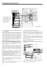
4. Connecting a television monitor or projector (MONITOR
OUT)
The DTR-6.4/5.4 is equipped with a simple Y/C separate circuit and
simple Y/C mixed circuit. Since both the signal from the S and V
inputs are output to the MONITOR OUT S output, if the television
or projector is equipped with an S video input, it is unnecessary to
connect the video connectors. If it is equipped with only a video
input, connect it to the MONITOR OUT V output.
Using an RCA video cable, connect the video input jack
(composite) of the device to the MONITOR OUT V jack of the
DTR-6.4/5.4. Or if the device has an S video input jack, connect it
to the MONITOR OUT S jack of the DTR-6.4/5.4 using an S video
cable. Or if the device has component video inputs, connect them to
the bank of COMPONENT VIDEO OUTPUT jacks on the DTR-
6.4/5.4.