


22
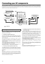
Connecting your AV components
INPUT 1INPUT 2
OUTPUT
COMPONENT VIDEO
Y
IN
IN
IN
IN
FRONT
SURR
CENTE
R
SUB
WOOFE
R
VIDEO 2
VIDEO 1
VIDEO 2
DVD
MONITOR
OUT
DVD
TAPE
L
R
VIDEO 3
VIDEO 1
V
VIDEO 3
IN
IN
IN
O
U
IN
IN
OUTOUT
OUTOUTOUT
S
ANTENNA
FM
75
AM
R
S
IR
IR OUT
56K
A
40K
B
ZONE 2
OUT
DC IN
24V 1A
L
R
ZONE 2
LINE OUT
ZONE 2
OPTICAL
1
2
OPTICAL
IN
OUT
12 V
TRIGGER
OUT
A
B
REMOTE
CONTROL
IN
COAXIAL
IN
COAXIAL
DIGITAL
CD
L
R
GND
PHONO
PR
PB
*
*
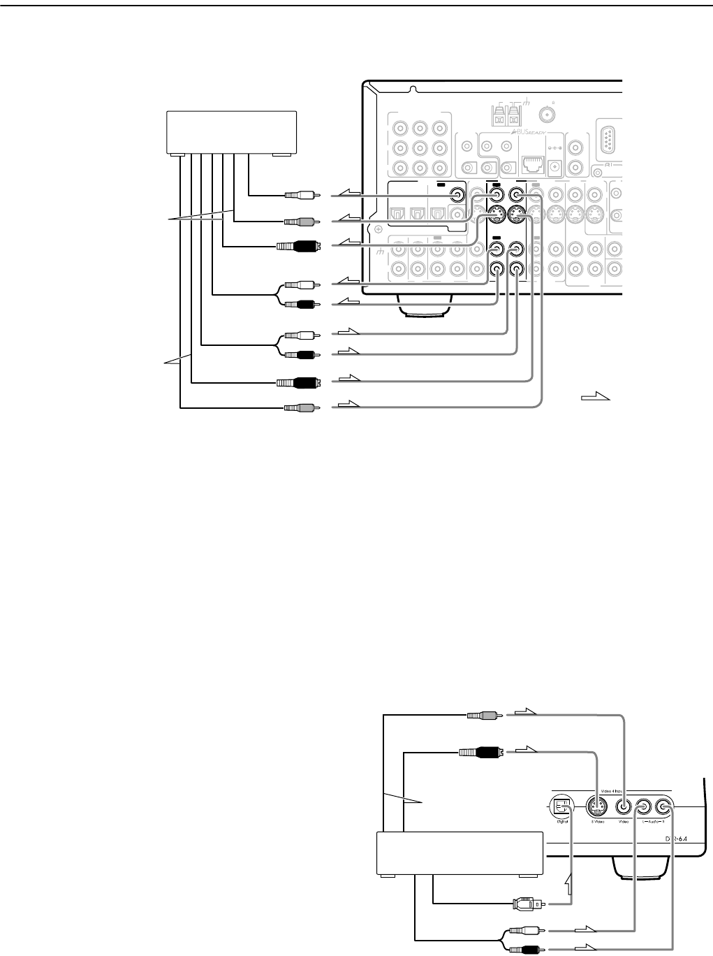
: Signal flow
L (white)
R (red)
L (white)
R (red)
S Video output
Video output
Video input
S Video input
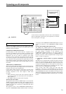
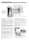
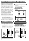
8. DVD recorder, other
digital video recording
device (VIDEO 2)
Digital audio
input (coaxial)
Analog audio
input
Analog audio
output
DTR-6.4 only
*You do not have to make
all the connection shown
on the illustration above.
For appropriate connection
for your components, see
“The flow of the video
signals” on page 19.
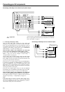
8. Connecting a DVD recorder or other digital video recording
device (VIDEO 2)
Using RCA video cables, connect the video output jack (composite)
of the device to the VIDEO 2 V IN jack of the DTR-6.4/5.4 and
connect the video input jack of the device to the VIDEO 2 V OUT
jack of the DTR-6.4/5.4. Or if the device has S video input and
output jacks, using S video cables, connect the S video output jack
of the device to the VIDEO 2 S IN jack of the DTR-6.4/5.4 and
connect the video input jack of the device to the VIDEO 2 S OUT
jack of the DTR-6.4/5.4. Or if the device has component video
outputs, connect them to the COMPONENT VIDEO INPUT 1 or 2
jacks on the DTR-6.4/5.4.
With the initial settings of the DTR-6.4/5.4, the VIDEO 2 input
source is set for the COMPONENT VIDEO INPUT 2 jacks.
If you connect the device to the COMPONENT VIDEO INPUT 1
jacks, this must be changed at “Input Setup” → “Component
Video” (see page 34).
Using RCA audio cables, connect the audio output jacks of the
device to the VIDEO 2 IN audio jacks of the DTR-6.4/5.4 and
connect the audio input jacks of the device to the VIDEO 2 OUT
audio jacks of the DTR-6.4/5.4. Make sure that you properly
connect the left channels to the L jacks and the right channels to the
R jacks.
If the device has a digital output, connect it to either the DIGITAL
IN COAXIAL jack or the DIGITAL IN OPTICAL jack of the DTR-
6.4/5.4 depending on the type of connector on the device.
With the initial settings of the DTR-6.4/5.4, nothing is allocated
as the digital input source for VIDEO 2 (----).
If you connect the digital audio output, be sure to make the
appropriate changes at “Input Setup” → “Digital Input” (see page
34).
If the device has a digital input, connect it to the DIGITAL OUT
jack of the DTR-6.4/5.4 for digital recording of the signal from the
digital input of the DTR-6.4/5.4.
Note:
The output from the DIGITAL OUT jack of the DTR-6.4/5.4 is only
the digital signal input to the DIGITAL IN jack.
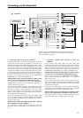
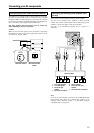
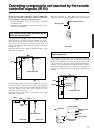
9. Connecting video camera, etc. (Video 4 Input)
Using an RCA video cable, connect the video output jack
(composite) of the device to the Video 4 Input Video jack of the
DTR-6.4/5.4. Or if the device has an S video output jack, connect it
to the Video 4 Input S Video jack of the DTR-6.4/5.4 using an S
video cable.
Using an RCA audio cable, connect the audio output jack of the
device to the Video 4 Input Audio jacks of the DTR-6.4/5.4. Make
sure that you properly connect the left channel to the L jack and the
right channel to the R jack.
If the device has an optical digital output, connect it to the Video 4
Input Digital jack of the DTR-6.4/5.4.
The Video 4 Input Digital is fixed to the OPTICAL input on the
front panel.
*
S Video output
Digital output
(optical)
9. Video camera/ Video game
(VIDEO 4 INPUT)
Video output
Analog output
R (red)
L (white)
*You do not have to make all the connection shown on the illustra-
tion above. For appropriate connection for your components, see
“The flow of the video signals” on page 19.