


21
Connecting your AV components
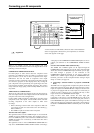
INPUT 1INPUT 2
OUTPUT
COMPONENT VIDEO
Y
IN
IN
IN
IN
FRONT
SURR
CENTER
SUB
WOOFER
VIDEO 2
VIDEO 1
VIDEO 2
DVD
MONITOR
OUT
DVD
TAPE
L
R
VIDEO 3
VIDEO 1
V
VIDEO 3
IN
IN
IN
OUT
IN
IN
OUTOUT
OUTOUTOUT
S
ANTENNA
FM
75
AM
IN
RS232
IR
IR OUT
56K
A
40K
B
ZONE 2
OUT
DC IN
24V 1A
L
R
ZONE 2
LINE OUT
ZONE 2
OPTICAL
1
2
OPTICAL
IN
OUT
12 V
TRIGGER
OUT
A
B
REMOTE
CONTROL
IN
COAXIAL
IN
COAXIAL
DIGITAL
CD
L
R
GND
PHONO
PR
PB
*
*
*
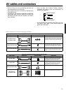
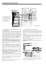
S Video input
Video input
Video output
S Video output
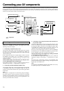
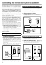
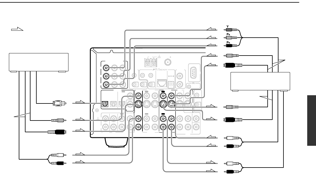
6. VCR (VIDEO 1)
L (white)
R (red)
L (white)
R (red)
L (white)
R (red)
Video output
S Video output
7. Satellite tuner or
television (VIDEO 3)
Analog audio input
Analog audio output
Digital audio output
(optical)
: Signal flow
Analog audio output
Component video output
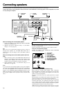
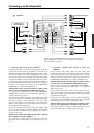
6. Connecting a video cassette recorder (VIDEO 1)
Using RCA video cables, connect the video output jack (composite)
of the video cassette recorder to the VIDEO 1 V IN jack of the
DTR-6.4/5.4 and connect the video input jack of the video cassette
recorder to the VIDEO 1 V OUT jack of the DTR-6.4/5.4. Or if the
video cassette recorder has S video input and output jacks, using S
video cables, connect the S video output jack of the video cassette
recorder to the VIDEO 1 S IN jack of the DTR-6.4/5.4 and connect
the video input jack of the video cassette recorder to the VIDEO 1 S
OUT jack of the DTR-6.4/5.4. Or if the video cassette recorder has
component video outputs, connect them to the COMPONENT
VIDEO INPUT 1 or 2 jacks on the DTR-6.4/5.4.
With the initial settings of the DTR-6.4/5.4, the VIDEO 1 input
source is set for the COMPONENT VIDEO INPUT 2 jacks.
If you connect the video cassette recorder to the COMPONENT
VIDEO INPUT 1 jacks, this must be changed at “Input Setup” →
“Component Video” (see page 34).
Using RCA audio cables, connect the audio output jacks of the
video cassette recorder to the VIDEO 1 IN audio jacks of the DTR-
6.4/5.4 and connect the audio input jacks of the video cassette
recorder to the VIDEO 1 OUT audio jacks of the DTR-6.4/5.4.
Make sure that you properly connect the left channels to the L jacks
and the right channels to the R jacks.
If you are connecting a digital output device to the VIDEO 1 jack
instead of a VCR, connect it to either the DIGITAL IN COAXIAL
jack or DIGITAL IN OPTICAL jack depending on the type of
connector on the device.
With the initial settings of the DTR-6.4/5.4, nothing is allocated
as the digital input source for VIDEO 1 (----).
If you connect the digital audio output, be sure to make the
appropriate changes at “Input Setup” → “Digital Input” (see page
34).
7. Connecting a satellite tuner, television, or settop box
(VIDEO 3)
Using an RCA video cable, connect the video output jack
(composite) of the device to the VIDEO 3 V IN jack of the DTR-
6.4/5.4. Or if the device has an S video output jack, connect it to the
VIDEO 3 S IN jack of the DTR-6.4/5.4 using an S video cable. Or
if the device has component video outputs, connect them to the
COMPONENT VIDEO INPUT 1 or 2 jacks on the DTR-6.4/5.4.
With the initial settings of the DTR-6.4/5.4, the VIDEO 3 input
source is set for the COMPONENT VIDEO INPUT 2 jacks.
If you connect the device to the COMPONENT VIDEO INPUT 1
jacks, this must be changed at “Input Setup” → “Component
Video” (see page 34).
Using an RCA audio cable, connect the audio output jack of the
device to the VIDEO 3 IN audio jacks of the DTR-6.4/5.4. Make
sure that you properly connect the left channel to the L jack and the
right channel to the R jack.
If the device has a digital output, connect it to either the DIGITAL
IN COAXIAL jack or the DIGITAL IN OPTICAL jack of the DTR-
6.4/5.4 depending on the type of connector on the device.
With the initial settings of the DTR-6.4/5.4, the VIDEO 3 input
source is set for digital input at the OPTICAL 2 jack (OPT 2).
If the digital connection is made at a different jack, this must be
changed at “Input Setup” → “Digital Input” (see page 34).
*You do not have to make all the connection shown on the illustration
above. For appropriate connection for your components, see “The flow
of the video signals” on page 19.