


Software Design
Dimmable Light Ballast with Power Factor Correction, Rev. 1
54 Freescale Semiconductor
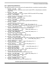
22. #define MIN_IGNITION_FREQ 45
...defines the minimum HRP frequency in kHz.
23. #define MAX2PREHEAT_RAMP 100
...represents the number of frequency steps between the maximum HRP frequency and the
preheat HRP frequency.
24. #define IGNITION_RAMP 2000
...represents the number of frequency steps between preheat HRP frequency and ignition HRP
frequency.
25. #define MIN_RUN_HRP_FREQ 50 /*see DLB_setup.xls */
...defines the minimum HRP frequency in kHz during run mode.
26. #define MAX_RUN_HRP_FREQ 100 /*see DLB_setup.xls */
...defines the maximum HRP frequency in kHz during run mode.
27. #define TUBE_CURR_MIN 10 /*see DLB_setup.xls */
...represents the minimum tube current.
28. #define TUBE_CURR_MAX 245 /*see DLB_setup.xls */
...represents the maximum tube current.
29. #define CURRFLT_MS 100
...sets the zero current checking interval in ms.
30. #define CURRFLT_CNT 3
...represents the number of fault states during run mode.
31. #define INGITION_CNT 3
...represents the number of fault states during tube ignition.
32. #define ADDMINITERVAL 100
...represents the interval of dimming value measurement in ms.
33. #define UC_REQUIRED_AN 390L
...represents the required DC-bus voltage in V.
34. #define UC_ALLOWED_MIN_AN 290L
...represents the minimum allowed DC-bus voltage in V.
35. #define UC_ALLOWED_MAX_AN 450L
...defines the maximum allowed DC-bus voltage in V.
36. #define UC_MAX_VAL_AN 458L
...represents the maximum value of the DC-bus voltage in V.
37. #define UC_START_PREHEAT_AN 370L
...represents the preheat DC-bus voltage in V.
38. #define UC_START_CYCLES_MAX 50
...represents the interval in ms in which the DC-bus voltage must reach the required value.
39. #define UC_START_RAMP_STEPS 30
...represents the number of steps needed to reach the DC-bus required value from the zero value.
40. #define PI_KP_START 10
...represents the proportional gain of the PI PFC stage regulator in the start phase.
41. #define PI_KI_START 3
...represents the integral gain of the PI PFC stage regulator in the start phase.
42. #define PI_KP_RUN 2
...represents the proportional gain of the PI PFC stage regulator in run mode.
43. #define PI_KI_RUN 1