


Hardware Design
Dimmable Light Ballast with Power Factor Correction, Rev. 1
26 Freescale Semiconductor
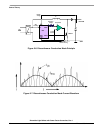
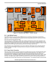
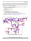
Figure 4-2. Dimmable Light Ballast with Hysteresis PFC HW variation — Hardware Block Diagram
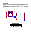
4.2.1 Input and PFC
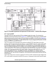
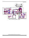
The input and the PFC part provide the DC-bus voltage to supply the inverter. The schematic for
hysteresis current control mode is shown in
Figure 4-3. The difference in discontinuous conduction mode
against hysteresis mode is that the gate of Q4 is connected to pin PWM1 of the MCU (see Figure A-2),
not to the output of the comparator. The input stage consists of an EMI filter and a single-phase full-bridge
rectifier. Although the PFC regulator is called an active filter, it does not suppress all harmonics. For this
reason, the EMI filter is placed at the input.
The PFC is based on the most popular non transformer isolated DC-DC boost (step-up) converter
topology. The PFC stage is built with input inductor L1, power MOSFET switch Q1, output rectifier diode
D1, and output capacitor C4. Capacitor C3 performs a filtering function. The input stage converts the
mains AC voltage, rectified by the diode bridge U1, to an output DC voltage on the output capacitor C4.
The current flowing through inductor L1 is sensed by the current sense resistor R4. There are two different
values of resistor R4, 1.5
Ω for rectified input voltage lower than half of DC-Bus voltage and 2.7Ω for higher
voltage. The voltage drop over the current sense resistor corresponds to the measured current. The
circuit, with resistors R3, R5, R7, R9, diodes D2 and D15, and capacitor C27 works as a mains
zero-crossing detector. It senses rectified mains voltage and generates zero-crossing pulses with an
amplitude of 5
volts. With the help of this detector, the microcontroller synchronizes its operation with the
mains frequency.
The DC-bus voltage sensor consists of resistors R1, R2, R6, and R8. It senses the output voltage of the
PFC, and its output is connected to the MCU AD converter. In hysteresis current control mode the output