


Software Design
Dimmable Light Ballast with Power Factor Correction, Rev. 1
40 Freescale Semiconductor
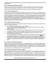
The register CONFIG2 sets:
– internal oscillator
– IRQ interrupt enabled
– IRQPUD must be 0 to connect the internal pullup resistor between IRQ pin and V
dd
.
• IRQ status and control register INTSCR sets:
– IMASK enable IRQ interrupt requests
– IRQ interrupt on falling edge only
• Analog to digital converter clock register (ADCLK)
– sets the ADC clock. ADC clock = bus clock / prescaler. The recommended value for the ADC
clock is 1
MHz.
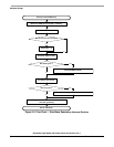
• PWM setup — void Set_PWM(void)
The subroutine initializes PWM values, and sets 0% duty cycle on PWM.
For a better understanding of PWM setup and logic, see 5.3.1.1 PWM Setup.
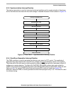
• HRP setup — void Set_HRP(void)
The subroutine initializes and sets HRP registers. For a better understanding of HRP setup and
logic, see
5.3.1.2 HRP Setup.
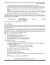
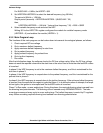
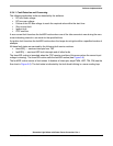
5.3.1.1 PWM Setup
The PWM module can generate two independent PWM signals used for PFC control. These signals are
edge-aligned. PWM resolution is one clock period which is dependent on the internal bus frequency
(BUSCLK) and a programmable prescaler (PRSC0, PRSC1). Also, programmable fault protection and
PWM signal polarity controls are provided.
For the application, the PWM is set to 40 kHz, resulting in 101 levels of PWM0 at a 4 MHz bus frequency.
Because of the hardware configuration, negative polarity control of the PWM output is required.
For proper operation of the PWM module, the following registers must be set:
• PWM counter modulus registers PMODH and PMODL hold a 12-bit unsigned number that
determines the maximum count for the up-only counter. It is set to 100.
• PVAL0H and PVAL0L registers determine duty cycle value (duty cycle = PVAL0/PMOD*100). In
initialization phase this is set to 0.
• PCTL1 register controls PWM enabling/disabling, the location of the PWM Fault bit, the loading of
new modulus, prescaler, and PWM values, and the PWM correction method.
In the application, PCTL1 is set as follows:
– Fault pin is PTB7
– interrupt is enabled
– load new values active
– module enabled
• PCTL2 register controls the PWM reload frequency, PWM channel enabling/disabling, the PWM
polarity, the PWM correction method, and the PWM counter prescaler. For safety reasons, some
of these register bits are buffered. The PWM generator will not use the prescaler value until the
LDOK bit has been set and a new PWM cycle is starting. The load frequency bits are not used until
the current load cycle is complete.
In the application, PCTL2 is set as follows:
– PWM0 enabled
– PWM1 enabled
– PWM0 negative polarity control
– reload frequency bits LDFQ0 and LDFQ1 to 0 — reload every PWM cycle