


Dimmable Light Ballast with Power Factor Correction, Rev. 1
Freescale Semiconductor 25
Chapter 4
Hardware Design
4.1 Hardware Implementation
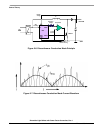
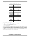
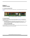
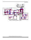
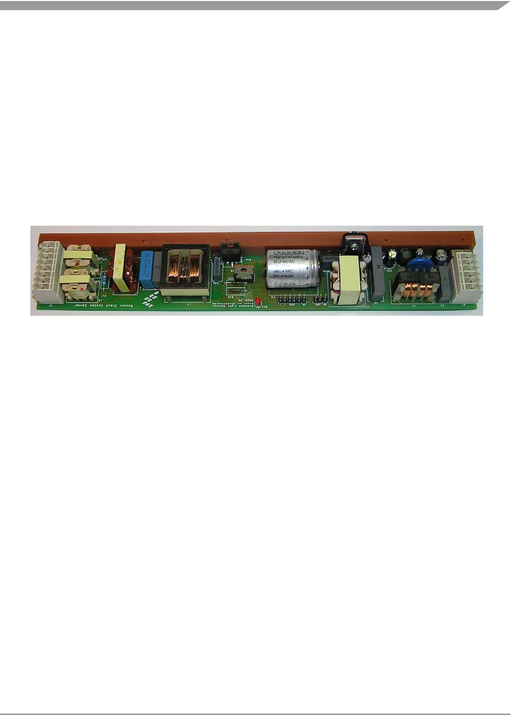
This chapter covers the system hardware implementation. The dimmable light ballast board is shown in
Figure 4-1.
Figure 4-1. Dimmable Light Ballast - Demo Board
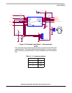
4.2 System Modules
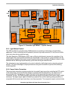
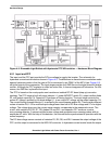
The light ballast system hardware is shown in the block diagram in Figure 4-2. It incorporates the
controller board, powered from AC line and fluorescent tubes. As can be seen, the controller board
contains four major parts:
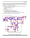
• Input and PFC (Input EMI Filter, Bridge Rectifier, Boost topology PFC circuit, DC-bus Voltage,
DC-bus Sensing, Mains Zero Crossing Sensing, Comparator Circuit, Buffer Circuit)
• Inverter (Half-bridge Drive, Resonant Circuit, Output Inductance Circuity, Different Voltage
Sensing, Tube Currents Sensing)
• Microcontroller (MC68HC908LB8)
• Power Supply (Switch Mode Power Supply)
Detailed descriptions of the individual parts of the controller boards follows. Note that the reference design
includes the PCB design files and bill of materials (BOM).