


Hardware Design
Dimmable Light Ballast with Power Factor Correction, Rev. 1
28 Freescale Semiconductor
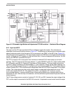
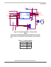
4.2.2 Inverter
The power inverter generates the proper voltage for the fluorescent tubes. The power inverter consists of
two MOSFET transistors driven by a half-bridge driver. It incorporates the half-bridge, a resonant circuit,
different voltage and tube current sensing, and output inductance circuity.
The half-bridge driver IR2106 from International Rectifier is electrically connected according to the
manufacturer’s recommendations. The half-bridge is supplied from the DC-bus voltage. It is controlled by
the TOP and BOT signals from the MCU.
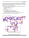
The half-bridge lamp resonant circuit consists of capacitor C15 and inductance L7. It provides preheating,
ignition, and running operating conditions by changing the operating frequency.
The tube voltage difference circuit consist of coils L3A, L3B, and L3D, resistors R21, R24, R22, and R151,
diode D8, and capacitor C17, and is used to sensing voltage differences between lamps. It helps to
recognize aging of the lamps.
Coils L4 and L5 and diodes D4 and D5 are for filament preheating. Diodes maintain a small offset to
remove the flickering effect. Coils L3A and L3D balance possible differences in current flow into tubes,
mainly at ignition stage. Devices R19, D7, R152, D6, C16, and R20 sense the current flow in tube 1 (and
similarly for tube 2).
For different tubes parameters, the tube currents are different. The ignition circuit formed by L3D, L3A,
and R17 balance the current. The compensation current flows through R17 until the tube currents are
equal, at which time the ignition of both tubes can be done reliably.
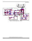
Tubes preheating heats the tubes to the desired temperature before startup. It decreases the wear-out
and increases the life-time and reliability in startup. Also, the voltage required for ignition is smaller.
Each tube has its own preheating circuity. Tube 1 uses L4. Tube 2 uses L5. The preheating voltage and
time is set-up in software and is controlled by the TOP and BOT signals from the HRP.
The flickering effect is caused by reducing the voltage to zero during the light ballast operation. To avoid
this, the Zener diodes D4 and D5 maintain a small voltage on both tubes at all times.
The output inductance circuity performs several important functions in the light ballast application. It helps
to ignite lamps, when tube parameters differ (due, for example, to different aging of the lamps). It removes
the flickering effect and provides filament preheating.