


Control Theory
Dimmable Light Ballast with Power Factor Correction, Rev. 1
16 Freescale Semiconductor
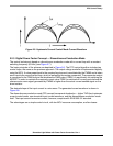
2.2.2 Digital Power Factor Concept — Hysteresis Current Control Mode
The control technique is based on hysteretic current control. The system operates in continuous
conduction mode with variable switching frequency (30–100 kHz) (see
Figure 2-5).
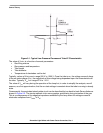
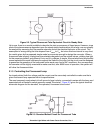
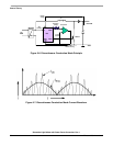
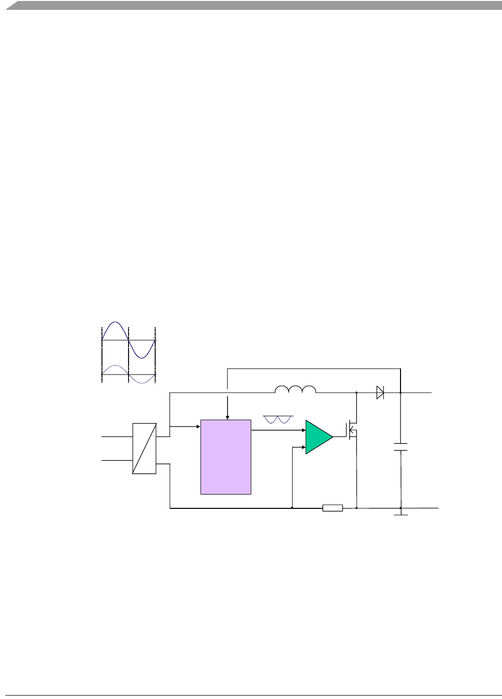
This PFC concept is designed to have the minimum of MCU performance requirements. The basic
principles of the scheme are depicted in
Figure 2-4. The PFC control algorithm includes two control loops,
a fast one for input current control and a slow one for output voltage control. The output voltage controller
is implemented digitally using the MCU. A value proportional to the required input current is modulated by
the PWM and is taken as an input to the current control loop, which is realized by the analogue
comparator. The comparator switches the MOSFET in order to maintain the required current value.
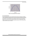
The desired shape of the input current is a sine wave. The generated current waveform is shown in
Figure 2-8.
A hysteresis current control mode PFC concept has several drawbacks, including variable MOSFET
switching frequency, non sinusoidal input current waveform and switching under current, which causes
higher losses than other PFC topologies.
The input current harmonics content, however, complies with EN 61000-3-2 standard.
The advantages are simple control circuit, low MCU resources consumption, continuous conduction
mode operation, and low total harmonic distortion (THD).
+ DC BUS
+
AC
LINE
AC
DC
MCU
Reference
Voltage
Actual
Current
Zero
Crossing
L
GND
Comparator
DC Bus
Voltage
-
Current Sensing
0
AC Line Voltage
AC Line Current
IC
ADC
PWM
+
MOSFET
Figure 2-4. Hysteresis Current Control Mode Principle