


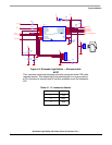
TOP
GND
BOT
Comp -
Comp Out
Tube Current 1
5V
Zero Detect
1
2
3
JP2
Luminance Level
5V
GND
Serial Data
GNDGND
R260
0R
VDD
1
VSS
2
PTC0/OSC1
3
PTC1/OSC2
4
PTC2/SHTDWN/IRQ
5
PTB0/TOP
6
PTB1/BOT
7
PTB2/FAULT
8
PTB3/PWM0
9
PTB4/PWM1
10
PTA6/ADC5/TCH0/KBI6
20
PTA5/RST/KBI5
19
PTA4/ADC4/KBI4
18
PTA3/ADC3/KBI3
17
PTA2/ADC2/KBI2
16
PTA1/ADC1/KBI1
15
PTA0/ADC0/KBI0
14
PTB7/VOUT/ADC6/FAULT
13
PTB6/V-
12
PTB5/V+
11
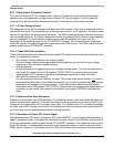
IC2
MC68HC908LB8-CASE_751D
1 2
C19
100nF
25V
GND
5V
5V
D11
LED
R28
1K8
R26
1K
R27
1K
GND
R30
13K
R29
11K
R31
3K9
5V
R33
10K
Serial Data
1
2
3
4
5
6
JP5
CONN/HDR/6X1
Tube Current 2
DCB Divider
R39
0R
Tube Voltage difference
R38
N/P
1 2
C9
100nF
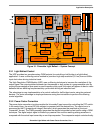
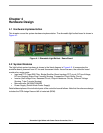
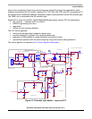
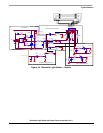
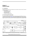
System Modules
Dimmable Light Ballast with Power Factor Correction, Rev. 1
Freescale Semiconductor 31
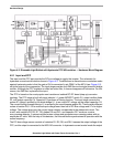
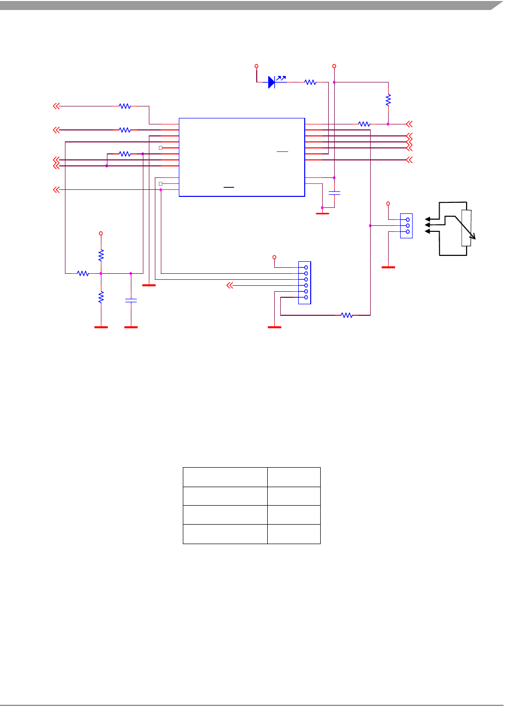
Figure 4-5. Dimmable Light Ballast — Microcontroller
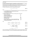
NOTE
The Luminance Level potentiometer should be connected to the PCB in the
required manner. This means that if the potentiometer is in a zero position,
a 0% Luminance is required and 0V must be available on pin 2 of connector
JP2.
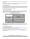
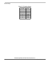
Table 4-1. J1 Luminance Header
Pin number Signal
1 +5V
2 PTA1
3 GND