


Introduction
Dimmable Light Ballast with Power Factor Correction, Rev. 1
Freescale Semiconductor 13
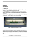
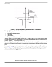
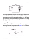
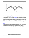
Figure 2-2. Typical Fluorescent Tube Equivalent Circuit in Steady State
Up to now, there is no model available to describe the start up sequence of these lamps. However, since
most of the phenomena are dependent upon the steady state characteristics of the lamp, one can simplify
the analysis by assuming that the passive networks control the electrical behavior of the circuit. This
assumption is wrong during the time elapsed from V
strike
to V
on
, but since this time interval is very short,
the results given by the proposed simple model are accurate enough to design the converter. When a
fluorescent tube is aging, its electrical characteristics degrade from the original values, yielding less light
for the same input power, and different V
strike
and V
on
voltages. A simple, low-cost electronic lamp ballast
cannot optimize the overall efficiency throughout the lifetime of the tube, but the circuit must be designed
to guarantee the operation of the lamp even under worst case “end of life” conditions. As a consequence,
the converter will be slightly oversized to make sure that, after 8000 hours of operation, the system will
still drive the fluorescent tube.
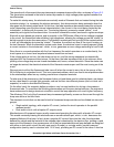
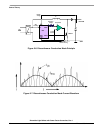
2.1.3 Controlling the Fluorescent Lamp
As already stated, both the voltage and the current must be accurately controlled to make sure that a
given fluorescent lamp operates within its specifications.
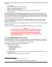
The most commonly used network is built around a large inductor, connected in series with the lamp, and
associated with a bimetallic switch generally named “the starter”.
Figure 2-3 gives the typical electrical
schematic diagram for the standard, line operated, fluorescent tube control.
Figure 2-3. Standard Ballast Circuit for Fluorescent Tube