


PFC Control Theory
Dimmable Light Ballast with Power Factor Correction, Rev. 1
Freescale Semiconductor 15
power, battery operated fluorescent tubes are driven with a single switch fly-back topology, but, the output
transformer is coupled to the tube by a capacitive network and the current through the lamp is alternating
current. However, the filaments (if any) cannot be automatically turned off by this simple configuration and
the global efficiency is downgraded accordingly.
Dual switch circuits are divided into two main topologies:
• Half-bridge, series resonant
• Current fed push-pull converter
The half-bridge is, by far, the most widely used in Europe (100% of the so-called “energy saving” lamps
and industrial applications are based on this topology), while the push-pull is the preferred solution in the
USA with around 80% of the electronic lamp ballasts using this scheme today.
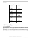
Both of these topologies have their advantages and drawbacks, the consequence for the associated
power transistors being not at all negligible, as shown by
Table 2-1. The half-bridge topology controlled
by the dedicated MC68HC908LB8 MCU is implemented in Chapter 3. For more details about electronic
lamp ballast theory see Reference [1.].
Table 2-1. Main Characteristics of the Dual Switch Topologies
Parameters Half-bridge Push-pull
V(BR)CER 700 V
1. These numbers are typical for operation on a 230 V supply.
(1)
1100 - 1600 V
(1)
Inrush Current 3 to 4 times I nom
2. I nom is the current into the transistors in steady state.
(2)
2 to 3 times I nom
(2)
tsi window 2.6 – 3.6 µs 1.9 – 2.3 µs
Drive High and Low side Low side only
Intrinsic Galvanic Isolation no yes
2.2 PFC Control Theory
2.2.1 Introduction
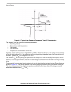
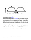
The most practical electronic systems contain a conventional single-phase full-bridge rectifier and an
input filter capacitor. It is well known that this type of circuit draws high current peaks from the power line
and produces a high level of harmonics. High total harmonic distortion (THD) and low power factor
therefore reduce the maximum power available from the mains and the efficiency of the electricity supply
networks. The European Normative EN 61000-3-2 defines the limits of the harmonic content of the input
current for mains supplied equipment.To meet the norms, new designs require an active PFC at the input.
Many specific integrated circuit devices (ICs) are available on the market to perform power factor
correction. This approach requires additional electronic components, which increases the system cost
and complexity. On the other hand, there is a way to implement PFC control using the MCU, in addition
to the MCU’s main control tasks, such as motor control. Digital PFC allows missing out these specific ICs,
thereby reducing the system cost. Another benefit of the software implementation is the potential for easy
modifications without changing the hardware.
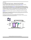
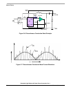
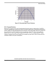
Two power factor correction approaches were implemented in this design, discontinuous conduction
mode and hysteresis current control mode. Each of these topologies has advantages and drawbacks.
Both topologies are described in the following.
NOTES: