


Control Theory
Dimmable Light Ballast with Power Factor Correction, Rev. 1
14 Freescale Semiconductor
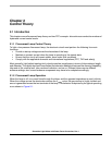
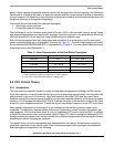
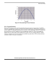
The operation of a fluorescent tube requires several components around the tube, as shown in Figure 2-3.
The gas mixture enclosed in the tube is ionized by means of a high voltage pulse applied between the
two electrodes.
To make this startup easy, the electrodes are actually made of filaments that are heated during the tube
ionization startup (i.e. increasing the electron emission), their disconnection being automatic when the
tube goes into the steady state mode. At this time, the tube impedance decreases toward its minimum
value (depending upon the tube internal characteristics), the current in the circuit being limited by the
inductance L in series with the power line. The starting element, commonly named “starter”, is an
essential part to ignite the fluorescent tube. It is made of a bimetallic contact, enclosed in a glass envelope
filled with a neon based gas mixture, and is normally in the OPEN state. When the line voltage is applied
to the circuit, the fluorescent tube exhibits a high impedance, allowing the voltage across the “starter” to
be high enough to ionize the neon mixture. The bimetallic contact gets hot, turning ON the contacts which,
in turn, will immediately de-ionize the “starter”. Therefore, the current can flow in the circuit, heating up
the two filaments. When the bimetallic contact cools down, the electrical circuit is rapidly opened, giving
a current variation in the inductance L which, in turn, generates an over-voltage according to Lenz’s law.
Since there is no synchronization with the line frequency (the switch operates on a random basis), the
circuit opens at a current level anywhere between maximum and zero.
If the voltage pulse is too low, the tube does not turn on, and the startup sequence is automatically
repeated until the fluorescent tube ionizes. At that time, the tube impedance falls to its minimum value,
yielding a low voltage drop across its end electrodes and, hence, across the switch. Since the starter can
no longer be ionized, the electrical network of the filaments remains open until the next turning on of the
circuit.
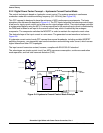
We must point out that the fluorescent tube turns off when the current is zero; this is the source of the
50
Hz flickering in a standard circuit. This is an important problem, which can lead to visual problems due
to the stroboscopic effect on any rotating machines or computer terminals.
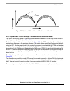
To take care of this phenomena, the fluorescent tubes, at least those used in industrial plants, are always
set on a dual basis in a single light spreader, and are fed from two different phases (real or virtual via a
capacitor) in order to eliminate the flickering.
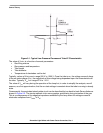
On the other hand, the magnetic ballast provides a very low cost solution for driving a low pressure
fluorescent tube. To overcome the flickering phenomenon and the poor startup behavior, the engineers
have endeavored to design electronic circuits to control the lamp operation at a much higher frequency.
The efficiency (Pin/Lux) of the fluorescent lamp increases significantly, as soon as the current through the
lamp runs above a few kilo Hertz.
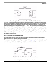
The electronic circuits that can be used to build a fluorescent lamp controller can be divided into two main
groups:
• Single switch topology, with unipolar AC current, (unless the circuit operates in the parallel
resonant mode)
• Dual switch circuit, with a bipolar AC output current
Manufacturers of fluorescent lamps usually recommend operating the tubes with a bipolar AC current.
This avoids constantly biasing the electrodes as an anode-cathode pair, which, in turn, decreases the
expected lifetime of the lamp. In fact, when a unipolar AC current flows into the tube, the electrodes
behave like a diode and the material of the cathode side is absorbed by the electron flow, yielding a rapid
wear out of the filaments. As a consequence, all of the line operated electronic lamp ballasts are designed
with either a dual switch circuit (the only one used in Europe), or a single switch, parallel resonant
configuration (mainly used in countries with 110
V lines), providing an AC current to the tubes. A few low