


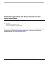


Dimmable Light Ballast with Power Factor Correction, Rev. 1
Freescale Semiconductor 11
Chapter 2
Control Theory
2.1 Introduction
This chapter covers fluorescent lamp theory and two PFC concepts - discontinuous conduction mode and
hysteresis current control mode.
2.1.1 Fluorescent Lamp Control Theory
To light a low-pressure fluorescent lamp, the electronic circuit must perform the following four main
functions:
• Provide a startup voltage across the electrodes of the lamp
• Maintain a constant current when the lamp is operating in the steady state
• Ensure that the circuit will remain stable, even under fault conditions
• Comply with the applicable domestic and international regulations (PFC, THD and safety)
Most generally, light ballast topology fairly closely matches target lamps in terms of tube wattage, length,
and diameter. The digital electronic lamp ballast includes also additional features like dimming capability,
tube end-of-life, startup fault, tube removed indication, and so on. Different tubes require different
software settings; also, some hardware components may have to be adapted accordingly.
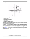
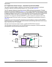
2.1.2 Fluorescent Lamp Operation
When the lamp is off, no current flows through the tubes, and the apparent impedance is nearly infinite.
When the voltage across the electrodes reaches the V
strike
value, the gas mixture is highly ionized and
an arc is generated across the two terminals of the lamp. This behavior is depicted by the typical operating
curve shown in
Figure 2-1.