


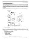
Software Implementation
Dimmable Light Ballast with Power Factor Correction, Rev. 1
Freescale Semiconductor 39
5.3 Software Implementation
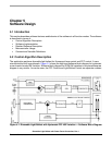
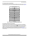
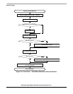
The general software implementation is illustrated in Figure 5-3. It incorporates the main routine entered
from Reset and three interrupt states. The main routine includes the initialization of the microcontroller
including PWM, HRP, ADC, and pins used in the application, and sets initial values for the PI regulator.
The infinite loop is performed as long as board remains connected to the mains and no fault conditions
are detected.
The interrupt states provide for trimming the internal oscillator, mains synchronization, reference sine
wave generation, and fault detection and processing.
OverFlow Interrupt
of Timer, Fault
Interrupt
Fault
Interrupt
Routine
PWM Reload Interrupt
Sinewave
Generation
Interrupt
Routine
done
MCU & Application
Initialization
Main
Infinite
Loop
RESET
done
IRQ Interrupt
Synchronization
Interrupt
Routine
done
done
Figure 5-3. Software Implementation
5.3.1 Initialization Setup
Prior to running the main program loop, the initialization setup sets the microcontroller operation mode
and peripherals. The quickest way to set and PWM is to use the auxiliary Excel sheet Reference [
4]. To
achieve the required system behavior and communication with peripherals, the following registers and
initial values are set.
• Set configuration registers CONFIG1 and CONFIG2 at the beginning of the initialization; they can
be written once only after each reset.
The register CONFIG1 sets:
– long COP time-out period
– enable LVI module
– disable STOP instruction